Get Latest Exam Updates, Free Study materials and Tips

1-The degree of closeness of the measured value of a certain quantity with its true value is known as
Accuracy
Precision
Standard
Sensitivity
(Ans: a)
2-Error of measurement =
True value – Measured value
Precision – True value
Measured value – Precision
None of the above
(Ans: a)
3-The ability by which a measuring device can detect small differences in the quantity being measured by it, is called its
Damping
Sensitivity
Accuracy
None of the above
(Ans: b)
4-The following term(s) is (are) associated with measuring devices
Sensitivity
Damping
Both ‘a’ and ‘b’
None of the above
(Ans: c)
5-To compare an unknown with a standard through a calibrated system is called
Direct comparison
Indirect comparison
both ‘a’ and ‘b’
None of the above
(Ans: b)
6-The following is an internationally recognized and accepted unit system
MKS
FPS
SI
All of the above
(Ans: c)
7-One yard = _____ inch
36
38
40
42
(Ans: a)
8-The following is a line standard of measurement
Measuring tape
Slip gauge
Micrometer
End bars
(Ans: a)
9-The ‘Wringing’ is due to
Atmospheric pressure
Molecular attraction
both ‘a’ and ‘b’
None of the above
(Ans: c)
10-The angle gauge by Dr. Tamlison consists of a set of
10 gauges
12 gauges
14 gauges
16 gauges
(Ans: a)
11-1 Angstrom (Å) = _____
10^-6m
10^-8m
10^-10m
10^-12m
(Ans: c)
12-The principle of ‘Interchangeability’ is normally employed for
Mass production
Production of identical parts
Parts within the prescribed limits of sizes
All of the above
(Ans: d)
13-Following is the theoretical size which is common to both the parts of a mating pair
Normal size
Actual size
Base size
All of the above
(Ans: c)
14-_____ is equal to the differences of the two limits of size of the part
Tolerance
Low limit
High limit
Design size
(Ans: a)
15-The amount by which the actual size of a shaft is less than the actual size of mating hole in an assembly
Clearance
Interference
Allowance
None of the above
(Ans: a)
16. If a steam pressure of 10 kg/cm2 is to be measured, the range of pressure gauge should be
A. ?10 kg/cm2 to + 10 kg kg/cm2
B. 0 to 10 kg kg/cm2
C. 5 to 11 kg kg/cm2
D. 0 to 20 kg kg/cm2
E. 0 to 100 kg kg/cm2
Answer: Option D
17. The degree of perfection used in instruments, the methods and the observations, is known as
A. Precision
B. Accuracy
C. Efficiency
D. Least count
E. Error
Answer: Option A
18. The accuracy depends upon
A. Precision of instrument
B. Precision of method
C. Good planning
D. All of the above
E. None of the above
Answer: Option D
19. A discrepancy is
A. The difference between a measurement and true value of the quantity measured
B. The difference between true value of the quantity and error
C. The difference between the measured value and actual value
D. The difference between the measured values of the same quantity
E. None of the above
Answer: Option D
20. If a measuring tape is too long as compared to standard, the error will be known as
A. Instrumental error
B. Personal error
C. Natural error
D. Manufacturing error
E. Superficial error
Answer: Option A
21. Natural error in measurement may be due to
A. Humidity
B. Temperature
C. Wind
D. Gravity
E. Any of the above
Answer: Option E
22. The errors which form inexperience of the observer are known as
A. Training errors
B. Handling errors
C. Personal errors
D. Accidental errors
E. Mistakes
Answer: Option E
23. If an error under the same conditions will always be of the same size and sign, it is known as
A. Training errors
B. Systematic errors
C. Cumulative error
D. Either of (A) and (B) above
E. Either of (B) and (C) above
Answer: Option E
24. The statement “The most probable value of an observed quantity available from a given set of observation is the one for which the sum of the square of errors is a minimum” is known as
A. Law of square probability
B. Pythogorus theorem
C. Principle of least squares
D. Law of errors
E. Principle of square errors
Answer: Option C
25. The maximum allowable limit that a measurement may vary from the true value is called
A. Permissible error
B. Expected error
C. Range of error
D. Least error
E. Safe error
Answer: Option A
26) The reliability of an instrument mean
a) The life of the instrument
b) The degree of repeatability within specified limits
c) The time interval between two responses of the instrument
d) None of these
ANSWER: b) The degree of repeatability within specified limits
27) Positive displacement flow meters are …………….flow meters.
a) Variable area flow
b) Differential pressure flow
c) Quantity flow
d) None of these
ANSWER: c) Quantity flow
28) For the analysis of …………. a polarograph is used.
a) Solids
b) Gases
c) Liquids
d) Moisture content in sand
ANSWER: a) Solids
29) Synchronization in a CRO means
a) Continuous monitoring of the trace
b) Adjustment of sweep frequency
c) Holding a pattern on the screens without creep
d) All of these
ANSWER: d) All of these
30) The materials used in the manufacture of thermistors are
a) Oxides of manganese and cobalt
b) Oxides of iron and zinc
c) Carbides of silicon and germanium
d) All of these
ANSWER: a) Oxides of manganese and cobalt
31) In a mechanical system, systematic error is produced by
a) Frictional loading
b) Inertial loading
c) Backlash
d) None of these
ANSWER: b) Inertial loading
32) By which of the following dynamometers are performance characteristics of pumps and compressors determined?
a) Driving dynamometer
b) Absorption dynamometer
c) Transmission dynamometer
d) None of these
ANSWER: a) Driving dynamometer
33) Which among the following statements is correct about LVDT?
a) It converts pressure into electrical output
b) It converts strain into electrical output
c) It converts linear displacement into electrical signal
d) All of these
ANSWER: c) It converts linear displacement into electrical signal
34) A strain gauge should have a high value of gauge factor
a) To reduce hysteresis effects
b) To give a linear relation between applied strains and resistance change
c) To increase sensitivity
d) To reduce or eliminate the effect of variation in ambient temperature
ANSWER: c) To increase sensitivity
35) The hot wire anemometer used for measuring gas velocities is a
a) Variable inductance transducer
b) Variable resistance transducer
c) Variable frequency transducer
d) Variable capacitance transducer
ANSWER: b) Variable resistance transducer
36. The desirable static characteristics of a measuring system are
A. Accuracy and resproducibility
B. Accuracy, sensitivity and reproducibility
C. Drift and dead zone
D. Static error
Answer:B. Accuracy, sensitivity and reproducibility
37. The ratio of maximum displacement deviation to full scale deviation of the instrument is called
A.Static sensitivity
B.Dynamic deviation
C.Linearity
D.Precision or accuracy
Answer:C.Linearity
38. ………. method is suitable for the measurement of a resistance of expected value less than one ohm
A.Substitution
B.Loss of charge
C.Wheatstone bridge
D.Kelvin’s double bridge
Answer:D.Kelvin’s double bridge
39. Which of the following can be measured by ‘Bolometers’
A.Thermal radiations
B.Electrical signals
C.Optical inputs
D.Temperature inputs
Answer:A.Thermal radiations
40. ………. frequency meter can be used for the measurement of radio frequency
A.Heterodyne
B.Weston
C.Electrical resonance
D.Any of the above
Answer:A.Heterodyne
41. Which of the following is caused by careless handling?
a) Systematic error
b) Gross error
c) Random error
d) None of the mentioned
Answer: b
Explanation: Gross errors are mostly due to lack of knowledge, judgment and care on the part of the experiment. That is Gross error is caused by careless handling.
42. ‘A system will be error free if we remove all systematic error’.
a) True
b) False
Answer: b
Explanation: Random errors will remain in a system even if we remove all systematic errors. Random errors are also known as residual errors.
43. Which of the following is not a fundamental quantity?
a) Length
b) Angle
c) Time
d) Luminous intensity
Answer: b
Explanation: Derived units are those expressed in terms of fundamental units. Primary or fundamental units cannot be expressed in terms of other units.
44. Which standard is fixed and used for industrial laboratories?
a) International standard
b) Primary standard
c) Secondary standard
d) Working standard
Answer: c
Explanation: Secondary standards are fixed and used in industrial laboratories. Working standards as its name suggests is used for day to day measurements. International standards are accepted internationally and primary standards are used in different parts of world which will not be accessible outside for calibration.
45. Which of the following error is caused by poor calibration of the instrument?
a) Random error
b) Gross error
c) Systematic error
d) Precision error
Answer: c
Explanation: Systematic errors are caused by poor calibration of instruments.
46. How systematic errors are eliminated?
a) Frequent measurement
b) Replacement of instrument
c) Finding mean of reading
d) Finding variance of reading
Answer: b
Explanation: The possible way of eliminating systematic error is the replacement of instruments. Systematic errors are caused by poor instrument calibration.
47. Which of the following represents an SI unit of luminous intensity?
a) Lumen
b) Candela
c) Dioptre
d) None of the mentioned
Answer: b
Explanation: SI unit of Luminous intensity is candela represented by cd. Luminous intensity is a Photometric quantity.
48. Starting position of an object is represented as x=5.1±0.2m and finishing position as y=6.9±0.3m. What will be the displacement and error in displacement?
a) Displacement = 1m, Error = 0.5m
b) Displacement = 2m, Error = 0.36m
c) Displacement = 1.8m, Error = 0.36m
d) Displacement = 1.5m, Error = 0.4m
Answer: c
Explanation: Displacement between two positions represented as x±Δx and y±Δy is Iy-xI and error in displacement is (Δx2 +Δy2)1/2.
49. Uncertainty in quantity X is given by ΔX. Then what will be the uncertainty in quantity R for which R=c.X?
a) |c|.ΔX
b) ΔX⁄|c|
c) ΔX
d) (ΔX)c
Answer: a
Explanation: Error of a Quantity which is a constant multiple of another quantity will be a constant multiple of error of first one.
50. ‘Zero error is an indication of instrumental error’.
a) True
b) False
Answer: a
Explanation: Zero error refers to a false indication of an instrument when the true value is zero and zero error can be treated as an instrumental error.
1. Seismic transducers are used to measure ______________
a) Displacement
b) Velocity
c) Acceleration
d) All of the mentioned
Answer: d
Explanation: Seismic transducers can be used to measure small displacement like vibrations, velocity and acceleration.
2. Seismic mass has freedom to move any direction.
a) True
b) False
Answer: b
Explanation: Movement of seismic mass is limited to one direction using a spring and damper system.
3. Relative displacement between housing frame and seismic mass in seismic transducer will be ____________
a) Xi(t)-Xm(t)
b) Xi(t)+Xm(t)
c) 2Xi(t)
d) 2Xm(t)
Answer: a
Explanation: Relative displacement between housing frame and seismic mass is the difference between absolute displacement of platform and displacement of mass.
4. Which of the following represents the application of spring?
a) To provide stability
b) To provide oscillatory motion
c) To provide restoring force
d) None of the mentioned
Answer: c
Explanation: Spring is used to provide restoring force to mass when device displaces.
5. Damper system is used to ______________
a) Produce oscillations
b) Limit oscillations
c) To produce displacement
d) For indication
Answer: b
Explanation: Damper systems are used to limit oscillations made by mass when the device is displaced.
6. Which of the following represents the correct relation for undamped natural frequency of system?
a) KM
b) (KM)1/2
c) K/M
d) (K/M)1/2
Answer: d
Explanation: Undamped natural frequency of a seismic transducer is the square root of the ratio of restoring force and mass.
7. Seismic transducer is only applicable for displacement measurement.
a) True
b) False
Answer: b
Explanation: Seismic transducers can be used to measure both displacement, velocity and acceleration with several changes on the mass-spring-damper system.
8. Which of the following spring-mass arrangement is used for displacement measurement?
a) Soft spring small mass
b) Soft spring large mass
c) Stiff spring small mass
d) Stiff spring large mass
Answer: b
Explanation: For displacement measurement, Soft spring large mass arrangement is used. Only in this arrangement, observable changes in the position of mass can be detected.
9. How bandwidth can be increased?
a) Lowering natural frequency
b) Increasing natural frequency
c) Doubling natural frequency
d) Bandwidth cannot be increased
Answer: a
Explanation: Natural frequency can be lowered for increasing bandwidth of seismic displacement transducer. Which means spring must be softer and mass should be large.
10. Seismic displacement transducers are not suitable for measuring ______________
a) Vibrating velocities
b) Static velocities
c) Dynamic velocities
d) None of the mentioned
Answer: a
Explanation: In amplitude response for zero and infinite frequencies amplitude becomes zero and we don’t get any flat amplitude response.
11. Strain gauge measurement involves __________
a) Wheatstone bridge
b) Kelvin bridge
c) De Sauty’s bridge
d) Anderson bridge
Answer: a
Explanation: Strain gauge makes use of the practical form of Wheatstone’s bridge to measure the strain developed by an element.
12. Load cell is used for the measurement of _______
a) area
b) force
c) mass
d) length
Answer: b
Explanation: The load cell is used in a semiconductor strain gauge for the measurement of force. Load cells measure the deformation that is produced by force or weight.
13. Strain is a _______
a) fractional change in volume
b) fractional change in area
c) fractional change in length
d) fractional change in height
Answer: c
Explanation: Strain is defined as the fractional change in length of a body. A change in resistance of the element is reflected in the form of strain of the gauge as well as the element.
14. Semiconductor strain gauge uses _______
a) rectifier circuitry
b) power electronics circuitry
c) ordinary bridge circuit
d) bridge circuit with temperature compensation
Answer: d
Explanation: The semiconductor strain gauge makes use of a Wheatstone practical bridge circuit along with temperature compensation. Output is made linear as the resistance characteristics with respect to strain are non-linear.
15. A semiconductor strain gauge consists of how many dummy gauges?
a) 2
b) 4
c) 6
d) 10
Answer: a
Explanation: The semiconductor strain gauge consists of two dummy gauges in the form of two arms of the Wheatstone bridge circuit. Dummy gauges are used for temperature compensation.
16. Metals in strain gauge construction have _______
a) non-linear temperature coefficient
b) linear temperature coefficient
c) tangential temperature coefficient
d) exponential temperature coefficient
Answer: b
Explanation: The metals used in a strain gauge construction have a linear temperature coefficient. A change in the temperature affects the resistance and varies the value of strain.
17. A Wheatstone bridge has _______
a) low sensitivity
b) zero sensitivity
c) high sensitivity
d) infinite sensitivity
Answer: c
Explanation: A Wheatstone bridge circuit has a high sensitivity for detecting very small variation in the values of resistance. We can connect the strain gauge in one of the arms of a Wheatstone bridge and measure the strain in terms of variation in resistance.
18. Load cells are calibrated such that _______
a) force varies inversely with resistance
b) force varies as the square of resistance
c) force remains constant with resistance
d) force varies directly with resistance
Answer: d
Explanation: The load cells in a semiconductor strain gauge are calibrated in such a way that the force or weight varies directly as the resistance. The strain gauge is arranged in the form of a bridge.
19. Load cell is sensitive to minute strains.
a) True
b) False
Answer: a
Explanation: A load cell responds to very minute variation in the value of strain. It is sensitive to high values of the load.
20. Mass of only about 20 kg can be measured by a load cell.
a) True
b) False
Answer: b
Explanation: Using a load cell a mass or weight of the order of 20 kg to 20,000 kg can be measured. By making use of appropriate load cells we can measure forces as high as 5 MN.
21. Electrical strain gauge works on the principle of __________
a) variation of resistance
b) variation of capacitance
c) variation of inductance
d) variation of area
Answer: a
Explanation: An electrical strain gauge works on the basis of change in resistance as a function of strain. The wire resistance increases with tension and reduces with compression.
22. The strain gauge is not bonded to the specimen.
a) True
b) False
Answer: b
Explanation: The gauge is under the same strain as that the specimen under test. As a result the strain gauge is bonded to the specimen.
23. Bonding element in a strain gauge must have __________
a) zero insulation resistance
b) low insulation resistance
c) high insulation resistance
d) infinite insulation resistance
Answer: c
Explanation: In a strain gauge, the bonding element must have a high value of insulation resistance. It should be immune to effects of moisture and must also have the ability to transmit strain.
24. Dynamic strain measurements use __________
a) brass iron alloy
b) iron aluminium alloy
c) nickel cadmium alloy
d) nickel chromium alloy
Answer: d
Explanation: Nickel chromium alloy is also known as a nichrome alloy. It contains 80 % of Nickel and 20 % of Chromium. Platinum is used for the temperature compensation of nickel chromium alloys.
25. Commonly used elements for wire strain gauges are __________
a) nickel and copper
b) nickel and gold
c) gold and brass
d) silver and aluminium
Answer: a
Explanation: Nickel and copper are the most commonly used elements for wire strain gauges. They comprise of 45 % of Nickel and 55 % of Copper. They exhibit a high value of specific resistance.
26. Cement is classified under __________
a) 4 types
b) 2 types
c) 6 types
d) 8 types
Answer: b
Explanation: Cement can be divided into two broad categories. They are as follows:
i) Solvent setting cement
ii) Chemically reacting cement.
27. Proper functioning of a strain gauge depends on __________
a) strain
b) stress
c) bonding
d) length of wire
Answer: c
Explanation: A strain gauge works properly only if the bonding material used is durable and keeps the gauge together to the surface of the material that is being tested.
28. Gauge factor is given by which of the following relation?
a) S = ΔR/RΔl
b) S = ΔRΔl/l
c) S = RΔl/l
d) S = ΔR/RΔl/l
Answer: d
Explanation: Gauge factor in a strain gauge is given by the relation
S = ΔR/RΔl/l
where, S is the gauge factor
R is the gauge wire resistance
∆R is the change in resistance
l is the length of the wire in unstressed condition
∆l is the change in length of the wire.
29. Poisson’s ratio is given by which of the following relation?
a) µ = –Δd/dΔl/l
b) µ = –ΔdΔl/l
c) µ = –dΔl/l
d) µ = –Δd/dΔl
Answer: a
Explanation: Poisson’s ratio is given by the relation
µ = –Δd/dΔl/l
where, d is the diameter of the cross-section of the wire
∆d is the change in the diameter of cross-section of the wire.
30. Proper bonding causes errors in strain gauges.
a) True
b) False
Answer: b
Explanation: Strain gauge is fixed onto the specimen by means of a bonding element. Cement is a commonly used adhesive. It transfers the strain from the specimen to the gauge sensing element.
31. What does the accelerometer measure?
a) Mass
b) Acceleration
c) Velocity
d) Distance
Answer: b
Explanation: The accelerometer is a type of inertial instrument that measures the acceleration in any given axes. The measured acceleration can be integrated over time to obtain velocity and distance.
32. What is the output given by an accelerometer if the instrument is accelerated upward with an acceleration of 7g?
a) 5g
b) 8g
c) 6g
d) 6.5g
Answer: b
Explanation: Accelerometer is used to measure acceleration of the vehicle and thus must be corrected for the Earth’s gravitational effect. If the accelerometer is being accelerated upward with an acceleration of 7g, then (a-G) = 7g – (-1g), and the instrument reads 8g.
33. Which accelerometer uses torquer coil and pick off supported by a flexure to measure acceleration?
a) MEMS accelerometer
b) Flexure pivot accelerometer
c) Vibrating beam accelerometer
d) Mechanical accelerometer
Answer: b
Explanation: The flexure pivot accelerometer is the most commonly used in aircraft systems. The sensitive element consists of a pendulum with a torquer coil and a pick off supported by torsional spring or flexure.
34. In flexure pivot accelerometer, the torque current is a measure of acceleration.
a) True
b) False
Answer: a
Explanation: The torquer coil in the accelerometer restore the pendulum to null, the torquer current being a measure of the restoring torque and, hence, of the acceleration.
35. Why do accelerometers that include fluid damping exhibit reduced damping?
a) State of fluid
b) Density
c) Pressure
d) Thermal characters
Answer: d
Explanation: Accelerometers that include fluid damping exhibit reduced bandwidth and additional thermal sensitivity due to changes in fluid characteristics. Thus flexure pivoted accelerometers are better than floated instruments.
36. An accelerometer can only measure acceleration in one direction?
a) True
b) False
Answer: a
Explanation: An accelerometer can only measure acceleration in one axes. In navigational systems comprising of accelerometers, three separate accelerometers are places with each on the three body axes of the aircraft.
37. Which of the following is true with respect to flexure pivot accelerometers?
a) Flexure must provide maximum resistance in the direction of input axis
b) Flexure must provide maximum resistance in the direction other than input axis
c) Torquer coil current measures the acceleration
d) Unbalanced accelerometer type
Answer: a
Explanation: The pivot or flexure supporting the pendulum must provide minimal restraint for the pendulum in the direction of the input axis while exhibiting high stiffness in the other two directions. The spring constant of the flexure or pivot generates a restoring force that reduces the gain of the electronic restoring loop.
38. Which of the following conditions cause rectification of vibration inputs?
a) Heating
b) Low voltage
c) High voltage
d) Low current
Answer: a
Explanation: Heating of torquer coil due to rebalance current can lead to rectification of vibration inputs and must often be compensated. A pulse rebalance torquer maintains constant heating.
39. What does silicon accelerometers use for proof mass sensing and for rebalancing?
a) Pivot
b) Flexure
c) Metalised wafers
d) Single crystal silicon frame
Answer: c
Explanation: The frame, proof mass and hinges are made with single crystal silicon. Metalised wafers are used to enclose this and also serve as electrodes for sensing proof mass and rebalancing.
40. Which type of rebalancing technique use voltage applied to pendulum and electrode for correction?
a) Charge forcing
b) Voltage forcing
c) Current forcing
d) Potential forcing
Answer: b
Explanation: In potential forcing, a potential is applied to the pendulum and to one or both the electrodes. The voltage establishes electric fields that induce the charge of the nonconducting pendulum. This causes a net force to act on the proof mass.
41. What will be the value measured by an accelerometer in free fall?
a) Zero
b) Infinite
c) Error
d) 9.81
Answer: a
Explanation: In a free fall the accelerometer will measure value=0. In a stationary state the accelerometer will measure the acceleration due to gravity as 9.81 m/s2 but in a free fall the acceleration of the falling accelerometer is also 9.81 m/s2 in the same direction, therefore the relative acceleration of the accelerometer becomes zero.
42. Which is the name of the accelerometer that is used to measure the gravity of the earth?
a) MPU6050
b) Gravitymeter
c) Gravitometer
d) Gravimeter
Answer: d
Explanation: Gravimeter are the accelerometer that is used to measure the gravity of the earth. The gravity of the earth varies from place to place depending upon the type of plain, plateau etc. This determination of acceleration due to gravity is called gravimetry.
43. What is the exact value of acceleration due to gravity taken in consideration?
a) 10 m/s2
b) 9.80665 m/s2
c) 9 m/s2
d) 0 m/s2
Answer: b
Explanation: The exact standard acceleration due to gravity is taken as 9.80665 m/s2. For general calculations it is assumed to be 10 m/s2. It the acceleration in which the earth pulls all the object present on the surface of earth. This acceleration varies at the poles of the earth.
44. Which element is mostly used in the capacitive accelerometers for sensing?
a) Germanium
b) Silicon
c) Lead
d) Carbon
Answer: b
Explanation: Silicon is mostly used in the capacitive accelerometers for sensing. It is relatively cheap and exhibits far better performance in the low frequency range. They can provide a higher stability and linearity when operated in servo mode.
45. MEMS stands for ________
a) Micro electric mechanical system
b) Micro electro mechanical system
c) Mini electro mechanical system
d) Mini electronic mechanical system
Answer: b
Explanation: MEMS stands for Micro electro mechanical system. Accelerometers, Gyroscopes and pressure sensors are MEMS sensors. It is a technology using which most of the accelerometers and other sensors are designed.
46. Accelerometers can be used for sensing mechanical vibrations.
a) True
b) False
Answer: a
Explanation: Accelerometers can be used for sensing mechanical vibrations. They can detect even very precise vibrations in the machine. Since the vibration is in single plane a two axis accelerometer is best suited for the measurement.
47. Acceleration is a ______ quantity.
a) scalar
b) vector
c) tensor
d) resistive
Answer: b
Explanation: Acceleration is a vector quantity. It is a vector quantity because it depends on both, magnitude of acceleration as well as the direction of acceleration. Had it been only dependent on magnitude, it would be a scalar quantity but it is not so.
48. MPU6050 in an example of which type of sensor?
a) Acceleration sensor
b) Proximity Sensor
c) Ultrasonic sensor
d) Laser sensor
Answer: a
Explanation: MPU6050 is an example of Acceleration sensor. It consists both 3 axis accelerometer and 3 axis gyroscope, which is capable of measuring very precise movements and accelerations.
49. Piezoelectric accelerometers converts ________ energy to ______energy.
a) mechanical, sound
b) mechanical, electrical
c) sound, electrical
d) sound, electrical
Answer: b
Explanation: Piezoelectric accelerometers converts mechanical energy to electrical energy. The word piezoelectric is derived from a Greek word “piezein” which means to press or squeeze. When any mechanical variable such as force or shock is applied on the input, then it produces subsequent electrical signals which is used to measure its magnitude.
50. Which is an example of accelerometer?
a) OptoNCDT ILR 1030
b) OptoNCDT 1420
c) ADXl 335
d) EddyNCDT 3301
Answer: c
Explanation: ADXl 335 is an example of accelerometer. OptoNCDTILR 1030 and OptoNCDT 1420 are laser sensor used for computing distance and objects placed at very high distances. EddyNCDT 3301 is a Eddy currents sensor.
1. If the displacement is measured with strain gauge then the number of strain gauge normally required are
A. One
B. Two
C. Three
D. Four
ANSWER: D. Four
2. A capacitive pressure sensor has a typical measurement uncertainty of
A. ± 0.2%
B. ± 0.4%
C. ± 0.1%
D. ± 0.8%
ANSWER: A. 0.2%
3. The instruments used for the measurement of pressure is/are
A. Bellows
B. Diaphragms
C. Fiber optic pressure sensors
D. All of these
ANSWER: D. All of these
4. Bourdon tube is used for the measurement of gauge pressure of
A. Gas
B. Liquid fluid
C. Solid
D. Both (a) and (b)
ANSWER: D. Both (a) and (b)
5. Dead weight gauge is used for the measurement of pressure of
A. About 1000 bar
B. About 2000 bar
C. About 5000 bar
D. About 7000 bar
ANSWER: D. About 7000 bar
6. The ionization gauge an instrument used for the measurement of
A. Very low pressure
B. Medium pressure
C. High pressure
D. Very high pressure
ANSWER: A. Very low pressure
7. When visual indication of pressure level is required then the instrument generally used is
A. Monometers
B. Diaphragm sensors
C. Bourdon tube
D. Resonant wire device
ANSWER: A. Monometers
8. For the measurement of high pressure with high accuracy the device used is
A. Manganin wire pressure
B. Ionization gauge
C. Dead weight gauge
D. Bourdon tubes
ANSWER: A. Manganin wire pressure
9. Advantage of passive instrument is
A. It does not need power supply
B. Cheap
C. Sensitive
D. Accurate
ANSWER: A. It does not need power supply
10. In McLeod gauge,
A. High pressure fluid is expanded to a low pressure which is read by the monometer technique
B. Low pressure fluid is compressed to a high pressure which is read by the bourdon technique
C. High pressure fluid is expanded to a low pressure which is read by the bourdon technique
D. Low pressure fluid is compressed to a high pressure which is read by the monometer technique
ANSWER: D. Low pressure fluid is compressed to a high pressure which is read by the monometer technique
11. Which of the following is detected using manometer devices?
a) Pressure difference between manometric and measuring liquid
b) pH difference between manometric and measuring liquid
c) Density difference between manometric and measuring liquid
d) None of the mentioned
Answer: a
Explanation: In manometer devices, pressure difference between manometric liquid and measuring liquid is obtained and it is equated to relation hϱg, ϱ is the mass density of the manometric liquid.
12. What is the difference between water and transformer oil as a manometric liquid?
a) Water is used for large pressure differential
b) Transformer oil is used for large pressure differential
c) Transformer oil has evaporation problems
d) Water has evaporation problems
Answer: d
Explanation: Both water and transformer oils are used in small pressure differential applications, but the difference is that water has problems related to relatively faster evaporation.
13. In which of the following categories be thin plate diaphragm included?
a) Primary transducer
b) Secondary transducer
c) Voltage measuring devices
d) Spring balance systems
Answer: a
Explanation: Primary transducers are devices which converts measurand into mechanical quantities. Diaphragm converts pressure into displacement which is a mechanical quantity.
14. Which of the following applications are suited for thin plate diaphragms?
a) Static pressure only
b) Dynamic pressure only
c) Both static and dynamic pressure with large frequency
d) Both static and dynamic pressure with small frequency
Answer: d
Explanation: Thin plate diaphragms can be used for measuring both static and dynamic pressures. But the limitation is that the frequency of application should be small.
15. Using a membrane for measuring pressure, which of the following represents correct relation for displacement?
a) (R2 ΔP)/4S
b) ΔP/4S
c) (R2 ΔP)/S
d) (R2 ΔP)/2
Answer: a
Explanation: R is the radius of membrane and S is the radial tension in N/m. Displacement will be an indication of applied pressure.
16. Which of the following quantities can be measured using bellows?
a) Absolute pressure
b) Gauge pressure
c) Differential pressure
d) All of the mentioned
Answer: d
Explanation: Bellows can be used for measuring Absolute pressure, Gauge pressure and Differential pressure of measuring medium. This is accomplished using two bellow chambers provided.
17. Which of the following conversion take place in bourdon tubes?
a) Pressure to displacement
b) Pressure to voltage
c) Pressure to strain
d) Pressure to force
Answer: a
Explanation: In bourdon tubes converts input pressure into displacement and displacement of the needle will be directly proportional to input pressure.
18. ‘Capsules are made from diaphragms’.
a) True
b) False
Answer: a
Explanation: Capsules are made by enclosing two identical corrugated diaphragms forming a closed chamber.
19. ‘In bellows pressure to displacement conversion takes place’.
a) True
b) False
Answer: b
Explanation: In bellows pressure to force conversion takes place, which is acted on bellows and can be measured for calculating applied pressure.
20. Which of the following devices convert pressure to displacement?
a) Diaphragm
b) Bellow
c) Capsule
d) Both diaphragm and capsule
Answer: d
Explanation: Both diaphragm and capsule convert pressure into displacement which can be measured using indicating instruments. Displacement will be proportional to applied pressure.
21. In _____________ velocity of fluid is constant on every point at a specific time.
a) Steady flow
b) Rotational flow
c) Non steady flow
d) None of the mentioned
Answer: a
Explanation: In steady flow fluid, velocity of all points will be constant at a specific time.
22. If all particle of fluid has a path parallel to the wall, it is known as ____________
a) Stream line flow
b) Laminar flow
c) Viscous flow
d) All of the mentioned
Answer: d
Explanation: If all particles of fluid have a parallel path with wall, it is called laminar flow which is also known as viscous flow and stream line flow.
23. Which of the following represents Reynolds number for laminar flow?
a) Less than 2000
b) Greater than 4000
c) Infinite
d) None of the mentioned
Answer: a
Explanation: Reynolds number is an indication of the flow of fluid, For a Reynolds number less than 2000, fluid is said to be in laminar flow. For greater than 4000 fluid is said to be in a turbulent flow.
24. Bernoulli’s theorem is applicable for fluid path with moderate frictional force.
a) True
b) False
Answer: b
Explanation: Bernoulli’s theorem is applied to obtain the total energy of the fluid at each of the two points separated by a distance and in a tapered pipeline. It assumes a frictionless path and viscous forces are negligible.
25. _____________ measures velocity at a point of fluid in a stream.
a) Venturi meter
b) pH meter
c) Pitot-Static tubes
d) None of the mentioned
Answer: c
Explanation: Pitot-static tubes are the devices used for measuring the velocity of the fluid.
26. Which of the following represents obstruction type flow measuring systems?
a) Centrifugal force type
b) Rotating vane system
c) Flow nozzle device
d) None of the mentioned
Answer: c
Explanation: In such systems, flow rate is measured by making an obstruction in the path of flow.
27. Static vane system causes pressure loss in flow.
a) True
b) False
Answer: a
Explanation: Static vane makes an obstruction in the path of fluid flow, which causes considerable pressure loss.
28. Which of the following represents the correct relation between flow rate and area of pipe?
a) Direct proportionality
b) Inverse proportionality
c) Equal
d) None of the mentioned
Answer: a
Explanation: Flow rate and area of cross section of pipe are directly proportional. That is when the area of pipe is increased flow rate also increases.
29. Which of the following converts flow to rotational motion?
a) Rotatic vane system
b) Rotameter flow system
c) Both rotameter flow system and rotatic vane system
d) None of the mentioned
Answer: a
Explanation: Rotatic vane system is used for measurement of flow rate of fluid, in which flow is converted into rotational motion.
30. Centrifugal force elements are used for ___________
a) High flow rate
b) Low flow rate
c) All range of flow rate
d) None of the mentioned
Answer: a
Explanation: Centrifugal force element for measuring flow rate is only applicable for high flow rate, below which it doesn’t produce any recognizable change.
31. Which of the following is correct for tactile sensors?
a) Touch sensitive
b) Pressure sensitive
c) Input voltage sensitive
d) Humidity sensitive
Answer: a
Explanation: Tactile sensors are those which sensitive to touch.
32. Change in output of sensor with change in input is ____________
a) Threashold
b) Slew rate
c) Sensitivity
d) None of the mentioned
Answer: c
Explanation: Sensitivity of a sensor is the change in output for a change in input.
33. Which of the following can be cause for non-zero output when zero input?
a) Bias
b) Slew
c) Offset
d) Offset or bias
Answer: d
Explanation: For ideal condition, zero input produces zero output.
34. Sensitivity of a sensor can be depicted by _______________
a) Niquist plot
b) Pole- zero plot
c) Bode plot
d) None of the mentioned
Answer: c
Explanation: Bode plot can be used for describing the sensitivity of a sensor.
35. Which of the following error is caused by a reversal of measured property?
a) Hysterisis
b) Noise
c) Digitization error
d) Quantization error
Answer: a
Explanation: Digitization error is caused by a reversal of measured value.
36. Smallest change which a sensor can detect is ____________
a) Resolution
b) Accuracy
c) Precision
d) Scale
Answer: a
Explanation: Resolution is the smallest change a sensor can detect.
37. Thermocouple generate output voltage according to ____________
a) Circuit parameters
b) Humidity
c) Temperature
d) Voltage
Answer: c
Explanation: Thermocouple is a device which is capable of producing output voltage according to input temperature.
38. Sensor is a type of transducer.
a) True
b) False
Answer: a
Explanation: Sensor is a device which enables measurement of input value.
39. Which of the following is not an analog sensor?
a) Potentiometer
b) Force-sensing resistors
c) Accelerometers
d) None of the mentioned
Answer: d
Explanation: All of the mentioned devices are analog sensors.
40. Measured property have no relation with error.
a) True
b) False
Answer: a
Explanation: Error of a system is independent of the measured value.
41. What is the full form of FIR in terms of signal filtering?
a) Finite impulse response
b) Finite impulse reduction
c) Finite impulse recombination
d) Filthy impulse response
Answer: a
Explanation: FIR in terms of signal filtering stands for Finite impulse response. It is a digital filter. The Impulse response of this filter is of a certain finite duration. The response settles to zero after some time.
42. Which frequency is attenuated in a Low-Pass filter?
a) High frequency
b) Low frequency
c) Mid-Range frequency
d) No frequency
Answer: a
Explanation: In a Low pass filter, High frequency is attenuated. It passes the frequencies only of Low-range and the frequency of high range is attenuated. The range may differ from filter to filter used for this purpose.
43. Which filter contains entirely passive elements?
a) Electrical filter
b) Mechanical filter
c) Digital filter
d) Optical filter
Answer: a
Explanation: Electrical filter contains entirely passive elements. These passive elements include resistors, inductors and capacitors. Electric filters were originally made from a combination of these passive elements.
44. Which is a signal generator module?
a) OptoNCDT ILR 1030
b) OptoNCDT1420
c) AD9850
d) EddyNCDT 3301
Answer: c
Explanation: AD9850 is a signal generator module. It can generate Sine signal. OptoNCDT ILR 1030 and OptoNCDT1420 are laser sensor used for computing distance and objects placed at very high distances. EddyNCDT 3301 is an Eddy currents sensor.
45. A system is said to be causal if its output depends on the future inputs.
a) True
b) False
Answer: b
Explanation: A system is said to be causal if its output does not depends on the future inputs. It is said to be causal only if it depends on the present and past inputs. If a system depends on the future input then the system is said to be non causal.
46. Capacitor can be used for signal filtering.
a) True
b) False
Answer: a
Explanation: Capacitor can be used for signal filtering. Capacitor is a device which stores charge. It can be used as a filter because it does not allow Direct current (DC) to pass through it, it only allows alternating current to pass through it.
47. Which family of filter has maximum flat frequency response?
a) Chebyshev filter
b) Bessel filter
c) Elliptic filter
d) Butterworth filter
Answer: d
Explanation: Butterworth filters have maximum flat frequency response among all other types of filter. Bessel filters have maximum flat phase delay. For a specific order and ripple, Elliptic filter has the steepest cut-off curve. Chebyshev filters show most appropriate ideal response.
48. Which family of filters have maximum flat phase delay?
a) Chebyshev filter
b) Bessel filter
c) Elliptic filter
d) Butterworth filter
Answer: b
Explanation: Bessel filters have maximum flat phase delay. Butterworth filters have maximum flat frequency response among all other types of filter. For a specific order and ripple, Elliptic filter has the steepest cut-off curve. Chebyshev filters show most appropriate ideal response.
49. What is the full form of IIR in terms of signal filtering?
a) Infinite impulse response
b) Infinite impulse reduction
c) Infinite impulse recombination
d) Instant impulse response
Answer: a
Explanation: IIR in terms of signal filtering stands for Infinite impulse response. It is a discrete time filter also known as digital filter. It depends linearly with the number of input samples and a finite number of previous filter inputs.
50. A system is said to be non causal if its present output depends on the future inputs.
a) True
b) False
Answer: a
Explanation: A system is said to be non causal if its present output depends on the future inputs. In non-causal system the inputs are the future responses of the system. If a system depends on the present and past inputs then the system is said to be causal system.
51. Which signal is obtained after integrating the unit step signal?
a) Square signal
b) Unit Step Signal
c) Ramp Signal
d) Parabolic Signal
Answer: c
Explanation: Ramp Signal is obtained after integrating the unit step signal. Integration of a curve gives the total area under the curve. For a standard unit step signal the value of signal is 0, so integration value is also 0. At index 0, the value of unit step signal is 1 but area under it is 0. So the integrated signal remains 0. But slowly the area under unit step signal increases constantly, so when it is integrated, gives out ramp function or ramp signal with constant slope.
52. Which signal is obtained after integrating the ramp signal (for x>0 in X-Axis)?
a) Square signal
b) Unit Step Signal
c) Ramp Signal
d) Parabolic Signal
Answer: d
Explanation: Parabolic Signal is obtained after integrating the ramp signal. Integration of a curve gives the total area under the curve.
Let us consider a ramp signal, Y=x
So its integration is (x2)/2 which clearly a parabolic signal.
53. Which signal is obtained after differentiating the ramp signal?
a) Square signal
b) Unit Step Signal
c) Ramp Signal
d) Parabolic Signal
Answer: b
Explanation: Unit Step Signal is obtained after differentiating the ramp signal. Differentiation gives the rate of change of a signal. Since integration and differentiation are reverse function of each other so integrating a unit step function also gives ramp signal back.
54. Which signal is obtained after differentiating the unit step signal?
a) UnitImpulse signal
b) Unit Step Signal
c) Ramp Signal
d) Parabolic Signal
Answer: a
Explanation: UnitImpulse signal is obtained after differentiating the unit step signal. Differentiation gives the rate of change of a signal. Since the only change occurs at point 0 in unit step signal so the differentiation of unit step signal becomes unit impulse signal at point 0.
55. Derivative of a unit step signal is zero everywhere.
a) True
b) False
Answer: b
Explanation: Derivative of a unit step signal is not zero everywhere. It is 0 at all points except at X=0 in XY plane. Differentiation gives the rate of change of a signal. Since the only change occurs at point 0 in unit step signal so the differentiation of unit step signal becomes unit impulse signal.
56. What is the slew rate of an ideal operational amplifier?
a) 0
b) 1
c) 100
d) Infinite
Answer: d
Explanation: The slew rate of an ideal operational amplifier is infinite. Slew rate of an operational amplifier is defined as the rate of change of output voltage with respect to time (i.e) dv/dt. An ideal operational amplifier takes no time to change the output, therefore dt=0. So dv/dt becomes infinite and hence an ideal operational amplifier has infinite slew rate.
57. What is the open loop gain of an ideal operational amplifier?
a) 0
b) 1
c) Infinite
d) -1
Answer: c
Explanation: The open loop gain of an ideal operational amplifier is infinite. Open loop gain of an operational amplifier is defined as output voltage divide by input voltage (Vout/Vin). In ideal case the operational amplifier produces infinite output voltage when very low input voltage is applied.
58. What is the phase difference between input signal and output signal when input is provided to the inverting terminal of the operational amplifier?
a) 0 degree
b) 90 degree
c) 180 degree
d) 45 degree
Answer: c
Explanation: There 180 degree phase difference between input signal and output signal when input is provided to the inverting terminal of the operational amplifier. When input is provided to the negative terminal it adds 180 degree phase shift to the input signal and inverts the input signal, that is why the terminal is also called as inverting terminal.
59. What is the slew rate of an operational amplifier whose output voltage increases by 9 volt in 18 micro second?
a) 0.5 Volt/microsecond
b) 5 Volt/microsecond
c) 50 Volt/second
d) 2 Volt/microsecond
Answer: a
Explanation: Given:
Change in voltage(dv)=9 Volt
Change in time(dt)= 18 micro second
Slew rate=dv/dt=9V/18 microsecond=0.5 volt/microsecond
60. A practical operational amplifier has infinite bandwidth.
a) True
b) False
Answer: b
Explanation: A practical operational amplifier does not have infinite bandwidth. It is so because at higher frequency signals the efficiency of amplification starts to decrease. The practical operational amplifier cannot amplify signals with very high frequency. Ideal operational amplifiers have infinite bandwidth.
61.An ideal Operational amplifier should have Infinite output resistance and zero input resistance.
a) True
b) False
Answer: b
Explanation: An ideal Operational amplifier should have zero output resistance and infinite input resistance. Infinite input resistance allows any input signal to drive the operational amplifier and zero output resistance facilitates the operational amplifier to drive infinite number of loads.
62. CMRR stands for ____
a) Common mode rejection ratio
b) Common mains rejection ratio
c) Common mode reluctance ratio
d) Common mode rejection rate
Answer: a
Explanation: CMRR stands for Common mode rejection ratio. It is the ability of the Operational Amplifier to reject the common mode signals in the inverting and non-inverting terminals. It is the ratio of differential voltage gain to common mode voltage gain.
63. Which of the integrated circuit mentioned below is the name of an operational amplifier?
a) BC541
b) LM741H
c) TIP122
d) TIP135
Answer: b
Explanation: LM741H is most commonly used operational amplifier. It comes in 8-pin TO-99 package with an operating voltage of +15 volt to -15 volt. It provides high voltage gain with a bandwidth of 1.5MHz.
64. PSRR stands for ________
a) Power Supply Relaxation Ratio
b) Power Supply Rejection Rate
c) Power Supply Rejection Ratio
d) Power Supply Rejecting Ratio
Answer: c
Explanation: PSRR stands for Power Supply Rejection Ratio. It is defined as the ratio of change in the input supply voltage to the equivalent output voltage it generates. An ideal operational amplifier has infinite power supply rejection ratio.
65. What is the common mode rejection ratio of an operational amplifier which has common mode gain=0.5 and differential gain=1200?
a) 600
b) 1200
c) 2400
d) 1200 db
Answer: c
Explanation: Given:
Common mode gain=0.5
Differential gain=1200
Common mode rejection ratio(CMRR)=differential gain(Ad) / common mode gain(Ac)
Ad/Ac=2400.
65. What is the slew rate of an operational amplifier whose output voltage increases by 6 volt in 12 micro second?
a) 0.5 Volt/microsecond
b) 5 Volt/microsecond
c) 50 Volt/second
d) 2 Volt/microsecond
Answer: a
Explanation: Given:
Change in voltage(dv)=6 Volt
Change in time(dt)=12 micro second
Slew rate=dv/dt=6V/12 microsecond=0.5 volt/microsecond
66. What is the slew rate of an operational amplifier whose output voltage increases by 5 volt in 15 micro second?
a) 0.33 Volt/microsecond
b) 3 Volt/microsecond
c) 50 Volt/second
d) 2 Volt/microsecond
Answer: a
Explanation: Given:
Change in voltage(dv)=5 Volt
Change in time(dt)=15 micro second
Slew rate=dv/dt=5V/15 microsecond=0.33 volt/microsecond
67. What is the common mode rejection ratio of an operational amplifier which has common mode gain=0.2 and differential gain=1300?
a) 650
b) 6500
c) 2400
d) 1200 db
Answer: b
Explanation: Given:
Common mode gain=0.5
Differential gain=1200
Common mode rejection ratio(CMRR)=differential gain(Ad)/common mode gain(Ac)
Ad/Ac=6500.
68. What is the common mode rejection ratio of an operational amplifier which has common mode gain=0.6 and differential gain=1000?
a) 650
b) 6500
c) 1666.66
d) 1200 db
Answer: c
Explanation: Given:
Common mode gain=0.6
Differential gain=1000
Common mode rejection ratio(CMRR)=differential gain(Ad) / common mode gain(Ac)
Ad/Ac=1666.66.
68. Common mode rejection ratio is defined as (common mode gain)/(differential mode gain).
a) True
b) False
Answer: b
Explanation: Common mode rejection ratio is defined as (differential mode gain)/ (common mode gain). It is the ability of the Operational Amplifier to reject the common mode signals in the inverting and non-inverting terminals.
1. First column elements of the Routh’s tabulation are 3, 5, -3/4, ½, 2. It means that there are:
a) Is one root in the left half of s-plane
b) Are two roots in the left half of s-plane
c) Are two roots in the right half of the s-plane
d) Is one root in the right half of s-plane
Answer: c
Explanation: Routh hurwitz criteria is used to find the stability of the system and this is determined by the number of roots in which the number of roots is equal to the number of sign changes.
2. Assertion (A): Feedback control system offer more accurate control over open-loop systems.
Reason (R): The feedback path establishes a link for input and output comparison and subsequent error correction.
a) Both A and R are true and R is correct explanation of A
b) Both A and R are true and R is not correct Explanation of A
c) A is True and R is false
d) A is False and R is true
Answer: a
Explanation: Feedback control system offers more accuracy and also reduces the gain of the system and establishes the link for input and output comparison and subsequent error correction.
3. Consider the following statements:
a) The effect of feedback is to reduce the system error
b) Feedback increases the gain of the system in one frequency range but decreases in the other
c) Feedback can cause a system originally stable to become unstable
d) Both a and c
Answer: d
Explanation: Feedback reduces error and can cause stable system to become unstable and also can make unstable system stable.
4. The Routh-Hurwitz criterion cannot be applied when the characteristic equation of the system contains any coefficients which is :
a) Negative real and exponential function
b) Negative real, both exponential and sinusoidal function of s
c) Both exponential and sinusoidal function of s
d) Complex, both exponential and sinusoidal function of s
Answer: b
Explanation: The Routh-Hurwitz criterion cannot be applied when the characteristic equation of the system contains any coefficients which is negative real, both exponential and sinusoidal function of s.
5. The following characteristic equation results in stable operation of the feedback system s3+4s2+10s+11=0
a) True
b) False
Answer: a
Explanation: Stable operation can be checked using the Routh-Hurwitz criterion where the first row of the the table is checked and with that.
6. Consider the following statements:
Routh-Hurwitz criterion gives:
1. Absolute stability
2. The number of roots lying on the right half of the s-plane
3. The gain margin and the phase margin
a) 1,2 and3
b) 1 and 2
c) 2 and 3
d) 1 and 3
Answer: b
Explanation: Routh-Hurwitz criterion gives absolute stability and number of roots lying on the right half of the s-plane.
7. The given characteristic equation s4+s3+2s2+2s+3=0 has:
a) Zero root in the s-plane
b) One root in the RHS of s-plane
c) Two root in the RHS of s-plane
d) Three root in the RHS of s-plane
Answer: c
Explanation: The stability analysis is done using Routh-Hurwitz criterion and hence the number of roots on the right is calculated.
8. Which of the following techniques is utilized to determine at the actual point at which the root locus crosses the imaginary axis?
a) Nyquist technique
b) Routh-Hurwitz technique
c) Nichol’s technique
d) Bode technique
Answer: b
Explanation: Routh-Hurwitz technique is utilized to determine at the actual point at which the root locus crosses the imaginary axis.
9. The characteristic equation of a control system is given by s6+2s5+8s4+12s3+20s2+16s+16=0 . The number of the roots of the equation which lie on the imaginary axis of s-plane:
a) 0
b) 2
c) 4
d) 6
Answer: c
Explanation: The stability analysis is done using Routh-Hurwitz criterion and hence the number of roots on the right is calculated.
10. Assertion (A): A linear, negative feedback control system is invariable stable if its open loop configuration is stable
Reason (R): the negative feedback reduces the overall gain of the feedback.
a) Both A and R are true and R is correct explanation of A
b) Both A and R are true and R is not correct Explanation of A
c) A is True and R is false
d) A is False and R is true
Answer: d
Explanation: A linear, negative feedback control system is not necessarily stable if its open loop configuration is stable.
11. What is the algebraic sum of the reference input and feedback?
a) Error Signal
b) Error Detector
c) Controlled system
d) Controlled output
Answer: a
Explanation: In the block diagram of a basic control system we see that the reference input is passed through Error detector or Comparator. The signal which leaves the same is the algebraic sum of reference input and feedback as the feedback wire is connected to the detector, so we call it error signal.
12. Feedback control systems are referred to as closed loop systems.
a) True
b) False
Answer: a
Explanation: Feedback control systems are also referred to as closed loop systems. In a closed loop, the actuating error signals, which is the difference between the input signal and the feedback signal is fed to the controller so as to reduce the error and bring the output of the system to the desired value.
13. Which principle does the linear system follow?
a) Principle of energy conservation
b) Principle of mass conservation
c) Principle of electromagnetism
d) Principle of superposition
Answer: d
Explanation: A linear system is one who obeys the principle of superposition. The principle of superposition states that the response produced by simultaneous application of two different forcing functions is equal to the sum of individual responses.
14. ______ control systems have unpredictable & non-repeatable.
a) Static
b) Dynamic
c) Deterministic
d) Stochastic
Answer: d
Explanation: Stochastic control systems are those who have unpredictable and non-repeatable response due to involvement of random parameters. Static systems is the system whose current output depends only on current input, dynamic system is a time dependent system and deterministic system’s response is predictable and repeatable.
15. The pressure inside the furnace is measured by _______
a) Gauge
b) Thermometer
c) Manometer
d) Barometer
Answer: a
Explanation: The pressure inside the furnace is measured by pressure gauge. In case the pressure increases or decreases beyond the desired value, the controller and the actuator will cause a change in the position of the damper.
16. On what difference does the pneumatic system works?
a) Speed
b) Pressure
c) Area
d) Length
Answer: b
Explanation: A pneumatic system works due to pressure difference of air or any other gas. Air at a pressure, pi is injected through the input manifold. It also consists of mass, coefficient of viscous friction and spring constant and the pressure difference created due to that, gives rise to pneumatic system.
17. In a thermal system, the temperature of the medium is ______
a) increasing
b) decreasing
c) zero
d) uniform
Answer: d
Explanation: To analyze a thermal system and determine its transfer function the temperature of the medium should be uniform. If the temperature is varying or zero the analysis will not be proper and a legitimate transfer function will not be the result.
18. How many parameters does process control refer to?
a) 1
b) 3
c) 5
d) 7
Answer: c
Explanation: Process control refers to control of five parameters which are level, flow, pressure, temperature, acidity of the process variable. A particular parameter has only one desired value.
19. What is the effect of feedback in the overall gain of the system?
a) Increases
b) Decreases
c) Zero
d) No change
Answer: b
Explanation: The feedback reduces the overall gain of the system. As soon as we introduce feedback in the system to make the system stable, gain is reduced.
20. In a temperature control system, what conversion in signal takes place?
a) Digital to Analog
b) Analog to Digital
c) Error to Digital
d) Error to Analog
Answer: b
Explanation: In a temperature control system, analog to digital conversion of signals take place. Automatic systems don’t understand analog signals as they only take digital inputs in the form of 0 & 1 so we use a analog to digital converter which converts the signal.
21. Which of the following is not the feature of modern control system?
a) Quick response
b) Accuracy
c) Correct power level
d) No oscillation
Answer: d
Explanation: For a good control system the speed of response and stability must be high and for the slow and sluggish response is not used and undesirable.
22. The output of the feedback control system must be a function of:
a) Reference input
b) Reference output
c) Output and feedback signal
d) Input and feedback signal
Answer: d
Explanation: Feedback control system has the property of reducing the error and that is by differencing the output with the desired output and as the equation of the output of the system is C=GR/1+GH.
23. The principle of homogeneity and superposition are applied to:
a) Linear time invariant systems
b) Nonlinear time invariant systems
c) Linear time variant systems
d) Nonlinear time invariant systems
Answer: c
Explanation: Superposition theorem states that for two signals additivity and homogeneity property must be satisfied and that is applicable for the LTI systems.
24. In continuous data systems:
a) Data may be continuous function of time at all points in the system
b) Data is necessarily a continuous function of time at all points in the system
c) Data is continuous at the inputs and output parts of the system but not necessarily during intermediate processing of the data
d) Only the reference signal is continuous function of time
Answer: b
Explanation: Continuous signals are the signals having values for the continuous time and if impulse response decays to zero as time approaches infinity, the system is stable.
25. A linear system at rest is subject to an input signal r(t)=1-e-t. The response of the system for t>0 is given by c(t)=1-e-2t. The transfer function of the system is:
a) (s+2)/(s+1)
b) (s+1)/(s+2)
c) 2(s+1)/(s+2)
d) (s+1)/2(s+2)
Answer: c
Explanation: c(t)=1-e-2t
R(s)=1/s-1/s+1
C(s)=1/s-1/s+2
Tf=2(s+1)/(s+2).
26. In regenerating the feedback, the transfer function is given by
a) C(s)/R(s)=G(s)/1+G(s)H(s)
b) C(s)/R(s)=G(s)H(s)/1-G(s)H(s)
c) C(s)/R(s)=G(s)/1+G(s)H(s)
d) C(s)/R(s)=G(s)/1-G(s)H(s)
Answer: d
Explanation: Regenerating feedback is positive feedback and it increases the infinitely and hence the speed of response of the system reduces.
27. A control system whose step response is -0.5(1+e-2t) is cascaded to another control block whose impulse response is e-t. What is the transfer function of the cascaded combination?
a) 1/(s+2)(s+1)
b) 1/(s+1)s
c) 1/(s+3)
d) 0.5/(s+1)(s+2)
Answer: a
Solution: Laplace transform is the transformation that transforms the time domain into frequency domain and of both the cascaded systems are 1/(s+1)(s+2).
28. A transfer function has two zeroes at infinity. Then the relation between the numerator(N) and the denominator degree(M) of the transfer function is:
a) N=M+2
b) N=M-2
c) N=M+1
d) N=M-1
Answer: b
Explanation: Zeroes at infinity implies two poles at origin hence the type of the system is two and degree of denominator is M=N+2.
29. When deriving the transfer function of a linear element
a) Both initial conditions and loading are taken into account
b) Initial conditions are taken into account but the element is assumed to be not loaded
c) Initial conditions are assumed to be zero but loading is taken into account
d) Initial conditions are assumed to be zero and the element is assumed to be not loaded
Answer: c
Explanation: When deriving the transfer function of a linear element only initial conditions are assumed to be zero, loading cannot be assumed to be zero.
30. If the initial conditions for a system are inherently zero, what does it physically mean?
a) The system is at rest but stores energy
b) The system is working but does not store energy
c) The system is at rest or no energy is stored in any of its part
d) The system is working with zero reference input
Answer: c
Explanation: A system with zero initial condition is said to be at rest since there is no stored energy.
31. Consider the block diagram shown below:
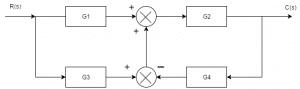
If the transfer function of the system is given by T(s)=G1G2+G2G3/1+X. Then X is:
a) G2G3G4
b) G2G4
c) G1G2G4
d) G3G4
Answer: b
Explanation: Use the technique of making two different block diagram by dividing two summers and use the approaches of shifting take off point and blocks.
32. For the block diagram given in the following figure, the expression of C/R is:
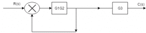
a) G1G2G3/1-G2G1
b) G1G2/1-G1G2G3
c) G1G2G3/1-G1G2G3
d) G1G2/G3(1-G1G2)
Answer: a
Explanation: Block diagram is being converted into signal flow graphs by considering each take off point as a node and each forward transfer function as forward gain.
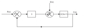
33. The transfer function from D(s) to Y(s) is :
a) 2/3s+7
b) 2/3s+1
c) 6/3s+7
d) 2/3s+6
Answer: a
Explanation: Y(s)/D(s)=2/3s+1/1+3*(2/3s+1)=2/3s+7.
34. The closed loop gain of the system shown in the given figure is :
a) -9/5
b) -6/5
c) 6/5
d) 9/5
Answer: b
Explanation: C(s)/R(s)=-3/1+3/2=-6/5.
35. The advantage of block diagram representation is that it is possible to evaluate the contribution of each component to the overall performance of the system.
a) True
b) False
Answer: a
Explanation: The advantage of the block diagram is that it is possible to get the contribution of each block to the overall performance of the system.
36. The overall transfer function from block diagram reduction for cascaded blocks is :
a) Sum of individual gain
b) Product of individual gain
c) Difference of individual gain
d) Division of individual gain
Answer: b
Explanation: Gain of block get multiplied when they are cascaded where cascaded means that the blocks are in series combination with no summer in between.
37. The overall transfer function of two blocks in parallel are :
a) Sum of individual gain
b) Product of individual gain
c) Difference of individual gain
d) Division of individual gain
Answer: a
Explanation: The gains get added as the blocks are connected in parallel with the summer in between and they are connected with the same sign.
38. Transfer function of the system is defined as the ratio of Laplace output to Laplace input considering initial conditions________
a) 1
b) 2
c) 0
d) infinite
Answer: c
Explanation: By definition transfer function is the ratio of the laplace output to the input but the initial conditions mainly the stored energy is zero.
39. In the following block diagram, G1=10/s G2=10/s+1 H1=s+3, H2=1. The overall transfer function is given by :
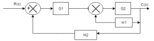
a) 10/11s2+31s+10
b) 100/11s2+31s+100
c) 100/11s2+31s+10
d) 100/11s2+31s
Answer: b
Explanation: C/R=G2G1/1+G2H2+G1G2H2
C/R=100/11s2+31s+100.
40. Oscillations in output response is due to :
a) Positive feedback
b) Negative feedback
c) No feedback
d) None of the mentioned
Answer: a
Explanation: Oscillations are the unwanted sinuoidal signals with high gain in positive feedback and s the damping factor is absent in the positive feedback system entirely oscillations are present.
1. Which of the following transfer function will have the greatest maximum overshoot?
a) 9/(s2+2s+9)
b) 16/(s2+2s+16)
c) 25/(s2+2s+25)
d) 36/(s2+2s+36)
Answer: d
Explanation: Comparing the characteristic equation with the standard equation the value of the damping factor is calculated and the value for the option d is minimum hence the system will have the maximum overshoot .
2. A system generated by ![]() The ramp component in the forced response will be:
The ramp component in the forced response will be:
a) t u(t)
b) 2t u(t)
c) 3t u(t)
d) 4t u(t)
Answer: b
Explanation: ![]()
Laplace transforming
sY(s) + 2Y(s)=4/s2
Taking the inverse Laplace transform the forced term is 2t u(t).
3. The system in originally critically damped if the gain is doubled the system will be :
a) Remains same
b) Overdamped
c) Under damped
d) Undamped
Answer: c
Explanation: ![]() hence due to this G lies between 0 and 1.
hence due to this G lies between 0 and 1.
4. Let c(t) be the unit step response of a system with transfer function K(s+a)/(s+K). If c(0+) = 2 and c(∞) = 10, then the values of a and K are respectively.
a) 2 and 10
b) -2 and 10
c) 10 and 2
d) 2 and -10
Answer: c
Explanation: Applying initial value theorem which state that the initial value of the system is at time t =0 and this is used to find the value of K and final value theorem to find the value of a.
5. The damping ratio and peak overshoot are measures of:
a) Relative stability
b) Speed of response
c) Steady state error
d) Absolute stability
Answer: b
Explanation: Speed of response is the speed at which the response takes the final value and this is determined by damping factor which reduces the oscillations and peak overshoot as the peak is less then the speed of response will be more.
6. Find the type and order of the system given below:
a) 2,3
b) 2,2
c) 3,3
d) None of the mentioned
Answer: Type = 2 which is the number of poles at the origin and order is the highest power of the characteristic equation.
7. A system has a complex conjugate root pair of multiplicity two or more in its characteristic equation. The impulse response of the system will be:
a) A sinusoidal oscillation which decays exponentially; the system is therefore stable
b) A sinusoidal oscillation with a time multiplier ; the system is therefore unstable
c) A sinusoidal oscillation which rises exponentially ; the system is therefore unstable
d) A dc term harmonic oscillation the system therefore becomes limiting stable
Answer: c
Explanation: Poles are the roots of the denominator of the transfer function and on imaginary axis makes the system stable but multiple poles makes the system unstable.
8. The forward path transfer function is given by G(s) = 2/s(s+3). Obtain an expression for unit step response of the system.
a) 1+2e-t+e-2t
b) 1+e-t-2e-2t
c) 1-e-t+2e-2t
d) 1-2e-t+e+2t
Answer: d
Explanation: C(s)/R(s) = s/(s2+3s+2)
C(s) = 1/s-2/s+1+1/s+2
c(t) = 1-2e-t+e+2t.
9. Find the initial and final values of the following function:
F(s) = 12(s+1)/s(s+2)^2(s+3)
a) 1,∞
b) 0,∞
c) ∞,1
d) 0,1
Answer: d
Explanation: Using final and initial values theorem directly to find initial and final values but keeping in mind that final value theorem is applicable for stable systems only.
10. The step response of the system is c(t) = 10+8e-t-4/8e-2t . The gain in time constant form of transfer function will be:
a) -7
b) 7
c) 7.5
d) -7.5
Answer: d
Explanation: Differentiating the equation and getting the impulse response and then taking the inverse Laplace transform and converting the form into time constant form we get K = -7.5.
11 . A unit integrator is applied to a modified system along with a ramp input. The modified value of the steady state error is 0.25. What was the initial value?
a) 0.05
b) 0.1
c) 0.15
d) 0.2
Answer:D
12 – The initial response when output is not equal to input is ______
a) Error response
b) Transient response
c) Dynamic response
d) Static response
Answer:B
13 – The steady state error for a unit step input is ________
a) 1/kp
b) 1/(1-kp)
c) 1/2kp
d) 1/(1+kp)
Answer:D
14 – For a unity feedback system, the open loop transfer function is G(s) = K(s+2)/s2 (s2+7s+12). What is the type of system?
a) One
b) Two
c) Three
d) Four
Answer:b
15 – 8. The For a unity feedback system the open loop transfer function is G(s) = K(s+2)/s2 (s2+7s+12). What is the value of Ka?
a) 12/k
b) k/12
c) k/6
d) 6/k
Answer:c
Solution: As limit s tends to zero : s2G(s) = K(s+2)/ (s2+7s+12) = k/6. Ka is the acceleration error constant which is calculated by the above method.
16 – For a system whose transfer function is G(s) =10/s (1+s), what are the dynamic error coefficients k2 & k3 respectively as k1 is infinity?
a) 11, 10.1
b) 10.1, 11
c) 10, 11.1
d) 9, 10.1
Answer:c
Solution :We should compare it with E(s)/R(s) = 1/k1+1/k2s+1/k3s2. G(s) = 10/s(1+s) is compared with the above equation which is the parent equation for calculating dynamic error constants where k1 comes as infinity and K2, K3 takes the value of 10 & 11.1 respectively.
17 – The Laplace transform of a parabolic signal is _______
a) 1
b) A/s3
c) A/s2
d) A/s
Answer:a
18 – The ramp input is applied to a unity feedback system with type number 1 and zero frequency 20. What is the percentage of steady state error?
a) 1%
b) 2%
c) 5%
d) 9%
Answer:c
19 – The steady state error for a unity feedback system for the input r(t) to the system G(s) = K(s+2)/s(s3+7s2+12s) is 6R/K. The input r (t) is _______
a) Rt2/2
b) Rt3/2
c) Rt5/2
d) Rt7/2
Answer:a
20 – Transient response analysis is done for_________ systems.
a) Unstable
b) Stable
c) Conditionally stable
d) Marginally stable
Answer:b
21 – Standard test signals in control system are:
a) Impulse signal
b) Ramp signal
c) Unit step signal
d) All of the mentioned
Answer:d
22 – The nature of transient response is revealed by ______________
a) Sine wave
b) Cos wave
c) Tan wave
d) Test signals
Answer:d
1. First column elements of the Routh’s tabulation are 3, 5, -3/4, ½, 2. It means that there are:
a) Is one root in the left half of s-plane
b) Are two roots in the left half of s-plane
c) Are two roots in the right half of the s-plane
d) Is one root in the right half of s-plane
Answer: c
Explanation: Routh hurwitz criteria is used to find the stability of the system and this is determined by the number of roots in which the number of roots is equal to the number of sign changes.
2. Assertion (A): Feedback control system offer more accurate control over open-loop systems.
Reason (R): The feedback path establishes a link for input and output comparison and subsequent error correction.
a) Both A and R are true and R is correct explanation of A
b) Both A and R are true and R is not correct Explanation of A
c) A is True and R is false
d) A is False and R is true
Answer: a
Explanation: Feedback control system offers more accuracy and also reduces the gain of the system and establishes the link for input and output comparison and subsequent error correction.
3. Consider the following statements:
a) The effect of feedback is to reduce the system error
b) Feedback increases the gain of the system in one frequency range but decreases in the other
c) Feedback can cause a system originally stable to become unstable
d) Both a and c
Answer: d
Explanation: Feedback reduces error and can cause stable system to become unstable and also can make unstable system stable.
4. The Routh-Hurwitz criterion cannot be applied when the characteristic equation of the system contains any coefficients which is :
a) Negative real and exponential function
b) Negative real, both exponential and sinusoidal function of s
c) Both exponential and sinusoidal function of s
d) Complex, both exponential and sinusoidal function of s
Answer: b
Explanation: The Routh-Hurwitz criterion cannot be applied when the characteristic equation of the system contains any coefficients which is negative real, both exponential and sinusoidal function of s.
5. The following characteristic equation results in stable operation of the feedback system s3+4s2+10s+11=0
a) True
b) False
Answer: a
Explanation: Stable operation can be checked using the Routh-Hurwitz criterion where the first row of the the table is checked and with that.
6. Consider the following statements:
Routh-Hurwitz criterion gives:
1. Absolute stability
2. The number of roots lying on the right half of the s-plane
3. The gain margin and the phase margin
a) 1,2 and3
b) 1 and 2
c) 2 and 3
d) 1 and 3
Answer: b
Explanation: Routh-Hurwitz criterion gives absolute stability and number of roots lying on the right half of the s-plane.
7. The given characteristic equation s4+s3+2s2+2s+3=0 has:
a) Zero root in the s-plane
b) One root in the RHS of s-plane
c) Two root in the RHS of s-plane
d) Three root in the RHS of s-plane
Answer: c
Explanation: The stability analysis is done using Routh-Hurwitz criterion and hence the number of roots on the right is calculated.
8. Which of the following techniques is utilized to determine at the actual point at which the root locus crosses the imaginary axis?
a) Nyquist technique
b) Routh-Hurwitz technique
c) Nichol’s technique
d) Bode technique
Answer: b
Explanation: Routh-Hurwitz technique is utilized to determine at the actual point at which the root locus crosses the imaginary axis.
9. The characteristic equation of a control system is given by s6+2s5+8s4+12s3+20s2+16s+16=0 . The number of the roots of the equation which lie on the imaginary axis of s-plane:
a) 0
b) 2
c) 4
d) 6
Answer: c
Explanation: The stability analysis is done using Routh-Hurwitz criterion and hence the number of roots on the right is calculated.
10. Assertion (A): A linear, negative feedback control system is invariable stable if its open loop configuration is stable
Reason (R): the negative feedback reduces the overall gain of the feedback.
a) Both A and R are true and R is correct explanation of A
b) Both A and R are true and R is not correct Explanation of A
c) A is True and R is false
d) A is False and R is true
Answer: d
Explanation: A linear, negative feedback control system is not necessarily stable if its open loop configuration is stable.
11. Stability of a system implies that :
a) Small changes in the system input does not result in large change in system output
b) Small changes in the system parameters does not result in large change in system output
c) Small changes in the initial conditions does not result in large change in system output
d) All of the above mentioned
Answer: d
Explanation: Stability of the system implies that small changes in the system input, initial conditions, and system parameters does not result in large change in system output.
12. A linear time invariant system is stable if :
a) System in excited by the bounded input, the output is also bounded
b) In the absence of input output tends zero
c) Both a and b
d) System in excited by the bounded input, the output is not bounded
Answer: c
Explanation: A system is stable only if it is BIBO stable and asymptotic stable.
13. Asymptotic stability is concerned with:
a) A system under influence of input
b) A system not under influence of input
c) A system under influence of output
d) A system not under influence of output
Answer: b
Explanation: Asymptotic stability concerns a free system relative to its transient behavior.
14. Bounded input and Bounded output stability notion concerns with :
a) A system under influence of input
b) A system not under influence of input
c) A system under influence of output
d) A system not under influence of output
Answer: a
Explanation: BIBO stability concerns with the system that has input present.
15. If a system is given unbounded input then the system is:
a) Stable
b) Unstable
c) Not defined
d) Linear
Answer: c
Explanation: If the system is given with the unbounded input then nothing can be clarified for the stability of the system.
16. Linear mathematical model applies to :
a) Linear systems
b) Stable systems
c) Unstable systems
d) Non-linear systems
Answer: b
Explanation: As the output exceeds certain magnitude then the linear mathematical model no longer applies.
17. For non-linear systems stability cannot be determined due to:
a) Possible existence of multiple equilibrium states
b) No correspondence between bounded input and bounded output stability and asymptotic stability
c) Output may be bounded for the particular bounded input but may not be bounded for the bounded inputs
d) All of the mentioned
Answer: d
Explanation: For non-linear systems stability cannot be determined as asymptotic stability and BIBO stability concepts cannot be applied, existence of multiple states and unbounded output for many bounded inputs.
18. If the impulse response in absolutely integrable then the system is :
a) Absolutely stable
b) Unstable
c) Linear
d) Stable
Answer: a
Explanation: The impulse response must be absolutely integrable for the system to absolutely stable.
19. The roots of the transfer function do not have any effect on the stability of the system.
a) True
b) False
Answer: b
Explanation: The roots of transfer function also determine the stability of system as they may be real, complex and may have multiplicity of various order.
20. Roots with higher multiplicity on the imaginary axis makes the system :
a) Absolutely stable
b) Unstable
c) Linear
d) Stable
Answer: b
Explanation: Repetitive roots on the imaginary axis makes the system unstable.
21. Roots on the imaginary axis makes the system :
a) Stable
b) Unstable
c) Marginally stable
d) Linear
Answer: c
Explanation: Roots on the imaginary axis makes the system marginally stable.
22. If the roots of the have negative real parts then the response is ____________
a) Stable
b) Unstable
c) Marginally stable
d) Bounded
Answer: d
Explanation: If the roots of the have negative real parts then the response is bounded and eventually decreases to zero.
23. If root of the characteristic equation has positive real part the system is :
a) Stable
b) Unstable
c) Marginally stable
d) Linear
Answer: b
Explanation: The impulse response of the system is infinite when the roots of the characteristic equation has positive real part.
24. A linear system can be classified as :
a) Absolutely stable
b) Conditionally stable
c) Unstable
d) All of the mentioned
Answer: d
Explanation: A system can be stable, unstable and conditionally stable also.
25. ___________ is a quantitative measure of how fast the transients die out in the system.
a) Absolutely stable
b) Conditionally stable
c) Unstable
d) Relative Stability
Answer: d
Explanation: Relative Stability may be measured by relative settling times of each root or pair of roots.
26. Assertion (A): Relative stability of the system reduces due to the presence of transportation lag.
Reason (R): Transportation lag can be conveniently handled by Bode plot.
a) Both A and R are true but R is correct explanation of A
b) Both A and R are true but R is correct explanation of A
c) A is true but R is false
d) A is false but R is true
Answer: b
Explanation: Transportation lag can be conveniently handled on Bode plot as well without the need to make any approximation.
27. Assertion (A): The phase angle plot in Bode diagram is not affected by the variation in the gain of the system.
Reason(R): The variation in the gain of the system has no effect on the phase margin of the system.
a) Both A and R are true but R is correct explanation of A
b) Both A and R are true but R is correct explanation of A
c) A is true but R is false
d) A is false but R is true
Answer: c
Explanation: The variation in the gain of the system has effect on the phase margin but phase plot is not affected.
28. A system has poles at 0.01 Hz, 1 Hz and 80Hz, zeroes at 5Hz, 100Hz and 200Hz. The approximate phase of the system response at 20 Hz is :
a) -90°
b) 0°
c) 90°
d) -180°
Answer: a
Explanation: Pole at 0.01 Hz gives -180° phase. Zero at 5Hz gives 90° phase therefore at 20Hz -90° phase shift is provided.
29. The constant M-circle represented by the equation x^2+2.25x+y^2=-1.25 has the value of M equal to:
a) 1
b) 2
c) 3
d) 4
Answer: c
Explanation: Comparing with the M circle equation we have the value of M =3.
30. What is the value of M for the constant M circle represented by the equation 8x2+18x+8y2+9=0?
a) 0.5
b) 2
c) 3
d) 8
31. The constant N loci represented by the equation x^2+x+y^2=0 is for the value of phase angle equal to:
a) -45°
b) 0°
c) 45°
d) 90°
Answer: d
Explanation: Centre = (-0.5, 0)
Centre of N circle is (-1/2, 1/2N)
N =tanα
α =90°.
32. All the constant N-circles in G planes cross the real axis at the fixed points. Which are these points?
a) -1 and origin
b) Origin and +1
c) -0.5 and 0.5
d) -1 and +1
Answer: a
Explanation: Centre of N circle is (-1/2, 1/2N)
N =tanα
Constant –N circles always pass through (-1, 0) and (0, 0).
33. Consider the following statements:
Nichol’s chart gives information about.
i. Closed loop frequency response.
ii. The value of the peak magnitude of the closed loop frequency response Mp.
iii. The frequency at which Mp occurs.
Which of the above statements are correct?
a) 2 and 3
b) 1 and 2
c) 1 and 3
d) 1,2 and 3
Answer: d
Explanation: Nichol’s chart gives information about closed loop frequency response, value of the peak magnitude of the closed loop frequency response Mp and the frequency at which Mp occurs.
34. Which one of the following statements is correct? Nichol’s chart is useful for the detailed study analysis of:
a) Closed loop frequency response
b) Open loop frequency response
c) Close loop and open loop frequency responses
d) None of the above
Answer: a
Explanation: Nichol’s chart is useful for the detailed study analysis of closed loop frequency response.
35. In a bode magnitude plot, which one of the following slopes would be exhibited at high frequencies by a 4th order all-pole system?
a) -80dB/decade
b) -40 dB/decade
c) 40 dB/decade
d) 80 dB/decade
Answer: a
Explanation: A 4th order all pole system means that the system must be having no zero or s-term in numerator and s4 terms in denominator. One pole exhibits -20dB/decade slope, so 4 pole exhibits a slope of -80 dB /decade.
36. Frequency range of bode magnitude and phases are decided by :
a) The lowest and higher important frequencies of dominant factors of the OLTF
b) The lowest and highest important frequencies of all the factors of the open loop transfer function
c) Resonant frequencies of the second factors
d) None of the above
Answer: d
Explanation: T. F. = Kp (1+Tds)
There is only one zero which will give slope of +20dB/decade.
37. OLTF contains one zero in right half of s-plane then
a) Open loop system is unstable
b) Close loop system is unstable
c) Close loop system is unstable for higher gain
d) Close loop system is stable
Answer: c
Explanation: OLTF contains one zero in right half of s-plane then Close loop system is unstable for higher gain.
38. The critical value of gain for a system is 40 and gain margin is 6dB. The system is operating at a gain of:
a) 20
b) 40
c) 80
d) 120
Answer: a
Explanation: Gm (dB) = 20logGM
GM =2
As we know, GM =K (marginal)/K (desired)
K desired =40/2 =20.
39. Nichol’s chart is useful for the detailed study and analysis of:
a) Closed loop frequency response
b) Open loop frequency response
c) Close loop and open loop frequency responses
d) open loop and Close loop frequency responses
Answer: a
Explanation: Nichol’s chart is useful for the detailed study and analysis of closed loop frequency response.
40. The roots of the characteristic equation of the second order system in which real and imaginary part represents the :
a) Damped frequency and damping
b) Damping and damped frequency
c) Natural frequency and damping ratio
d) Damping ratio and natural frequency
Answer: b
Explanation: Real part represents the damping and imaginary part damped frequency.
41. Which among the following is a unique model of a system?
a) Transfer function
b) State variable
c) Block diagram
d) Signal flow graphs
Answer: a
Explanation: Transfer Function is defined as the ratio of the Laplace output to the Laplace input with the zero initial conditions and is a unique model of the system.
42. Which among the following is a disadvantage of modern control theory?
a) Implementation of optimal design
b) Transfer function can also be defined for different initial conditions
c) Analysis of all systems take place
d) Necessity of computational work
Answer: d
Explanation: Modern control theory is also not best suited in every respect it has also some disadvantages and the major disadvantage is that it requires computational work.
43. According to the property of state transition method, e0 is equal to _____
a) I
b) A
c) e-At
d) -eAt
Answer: c
Explanation: By definition state transition matrix is defined as e-At and this is the matrix that comes into the picture when the total response is considered that is with the free response and forced response.
44. Which mechanism in control engineering implies an ability to measure the state by taking measurements at output?
a) Controllability
b) Observability
c) Differentiability
d) Adaptability
Answer: b
Explanation: Observability and controllability are the two methods to check the output response characteristics and observability in control engineering implies an ability to measure the state by taking measurements at output.
45. State model representation is possible using _________
a) Physical variables
b) Phase variables
c) Canonical state variables
d) All of the mentioned
Answer: d
Explanation: State model representation is the representation of the control system is the form of the state variables and state vectors and is possible using physical variables, phase variables and canonical state variables.
46. Which among the following constitute the state model of a system in addition to state equations?
a) Input equations
b) Output equations
c) State trajectory
d) State vector
Answer: b
Explanation: Output Equations constitute the state model of a system in addition to state equations and for the complete state model mainly input model, output model and state models are required.
47. Which among the following plays a crucial role in determining the state of dynamic system?
a) State variables
b) State vector
c) State space
d) State scalar
Answer: a
Explanation: State Variables are the integral part of the state variable analysis and plays a crucial role in determining the state of dynamic system.
48. Which among the following are the interconnected units of state diagram representation?
a) Scalars
b) Adders
c) Integrator
d) All of the mentioned
Answer: d
Explanation: Scalars, adders and integrator are the interconnected units of state diagram representation and this representation helps in determination of the state of the control system.
49. State space analysis is applicable even if the initial conditions are _____
a) Zero
b) Non-zero
c) Equal
d) Not equal
Answer: b
Explanation: State space analysis is the analysis different from the transfer function approach as it has state variables and state vectors used for the analysis and can be used even if initial conditions are non-zero.
50. Conventional control theory is applicable to ______ systems
a) SISO
b) MIMO
c) Time varying
d) Non-linear
Answer: a
Explanation: The major advantage of state space analysis is that it can be applied to MIMO systems also while the conventional control theory that is transfer function approach is applicable to the SISO systems only.
Prepare For Your Placements: https://lastmomenttuitions.com/courses/placement-preparation/
![]()
/ Youtube Channel: https://www.youtube.com/channel/UCGFNZxMqKLsqWERX_N2f08Q
Follow For Latest Updates, Study Tips & More Content!
Not a member yet? Register now
Are you a member? Login now