Get Latest Exam Updates, Free Study materials and Tips


1.It is preferable to connect bulbs in series or in parallel?
a) Series
b) Parallel
c) Both series and parallel
d) Neither series nor parallel
Answer: b
Explanation: Bulbs are connected in parallel so that even if one of the bulbs blow out, the others continue to get a current supply.
5.Batteries are generally connected in______
a) Series
b) Parallel
c) Either series or parallel
d) Neither series nor parallel
Answer: a
Explanation: Batteries are generally connected in series so that we can obtain the desired voltage since voltages add up once they are connected in series.
6.In a _________ circuit, the total resistance is greater than the largest resistance in the circuit.
a) Series
b) Parallel
c) Either series or parallel
d) Neither series nor parallel
Answer: a
Explanation: In series circuits, the total resistance is the sum of all the resistance in the circuit, hence the total is greater than the largest resistance.
7.In a ____________ circuit, the total resistance is smaller than the smallest resistance in the circuit.
a) Series
b) Parallel
c) Either series or parallel
d) Neither series nor parallel
Answer: b
Explanation: in a parallel circuit, the equivalent resistance=1/sum of the reciprocals of all the resistances in the circuit. Hence it is smaller than the smallest resistance in the circuit.
8.Which is the most cost efficient connection?
a) Series
b) Parallel
c) Either series or parallel
d) Neither series nor parallel
Answer: a
Explanation: The advantage of series-connections is that they share the supply voltage, hence cheap low voltage appliances may be used.
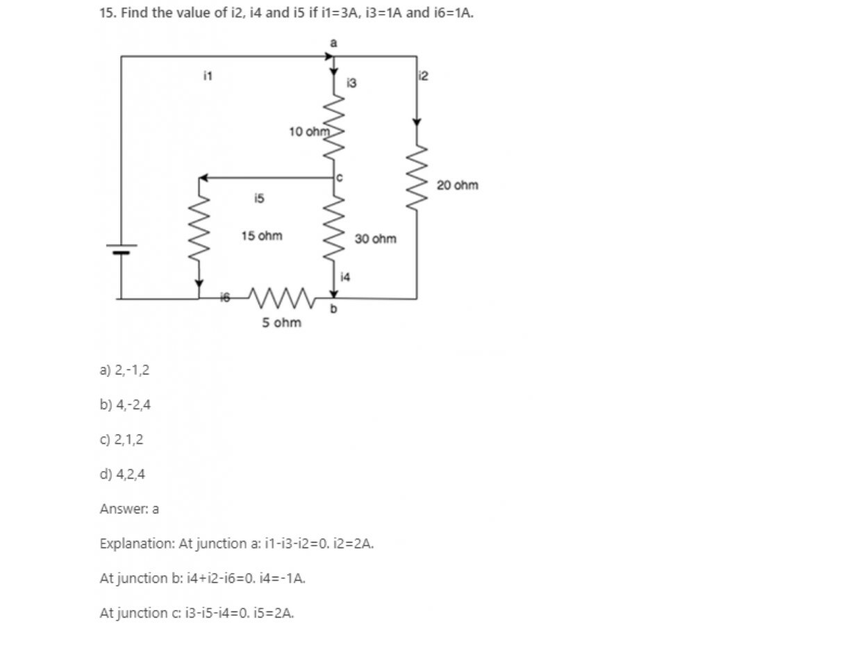
16. What is the value of current if a 50C charge flows in a conductor over a period of 5 seconds?
a) 5A
b) 10A
c) 15A
d) 20A
Answer: b
Explanation: Current=Charge/Time. Here charge = 50c and time = 5seconds, so current = 50/5 = 10A.
17. KCL deals with the conservation of?
a) Momentum
b) Mass
c) Potential Energy
d) Charge
Answer: d
Explanation: KCL states that the amount of charge entering a junction is equal to the amount of charge leaving it, hence it is the conservation of charge.
18. KCL is applied at _________
a) Loop
b) Node
c) Both loop and node
d) Neither loop nor node
Answer: b
Explanation: KCL states that the amount of charge leaving a node is equal to the amount of charge entering it, hence it is applied at nodes.
a) Planar networks
b) Non-planar networks
c) Both planar and non-planar
d) Neither planar nor non-planar
Answer: c
Explanation: KCL is applied for different nodes of a network whether it is planar or non-planar.
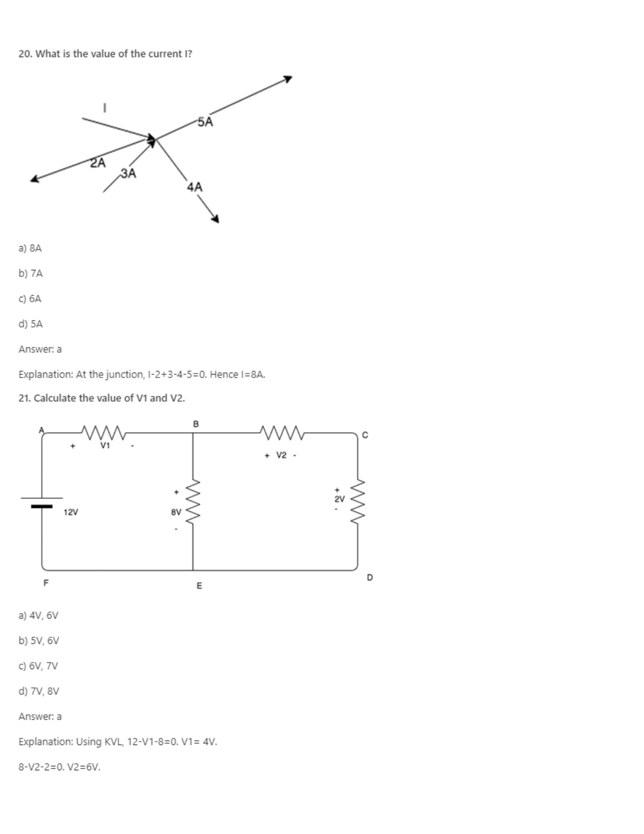
22. KVL deals with the conservation of?
a) Mass
b) Momentum
c) Charge
d) Energy
Answer: d
Explanation: KVL states that the sum of the potential energy and taken with the right sign is equal to zero, hence it is the conservation of energy since energy doesn’t enter or leave the system.
a) 0V
b) Infinity
c) 1V
d) 2V
Answer: a
Explanation: According to KVL, the sum of the voltage over any closed loop is equal to 0.
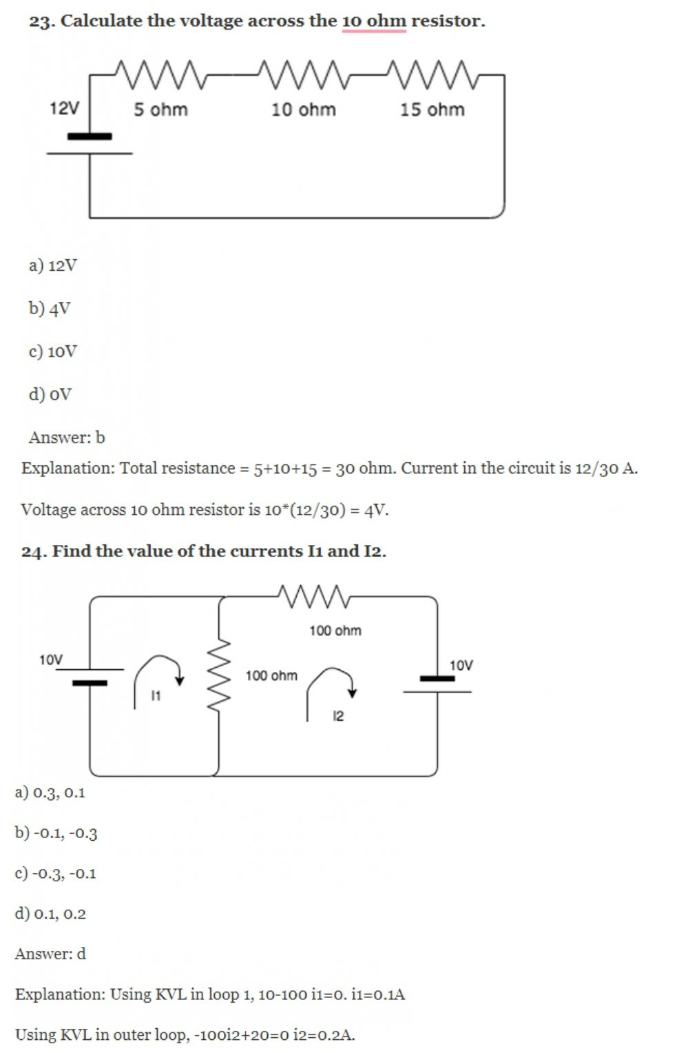
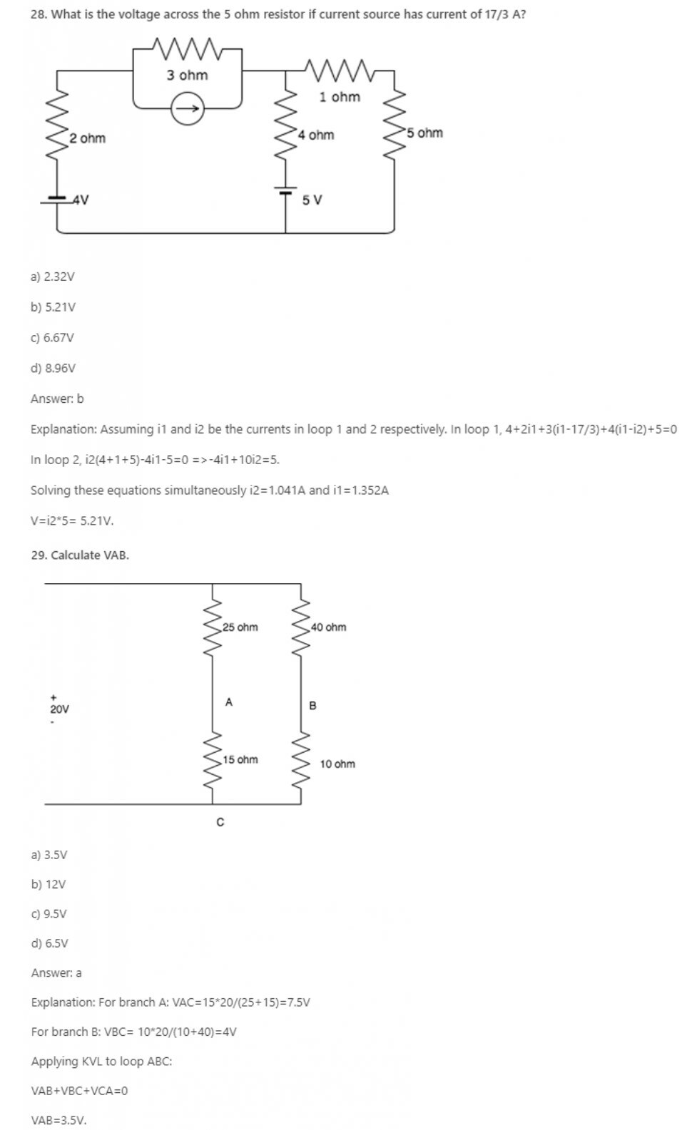
26. What is the basic law that has to be followed in order to analyze the circuit?
a) Newton’s laws
b) Faraday’s laws
c) Ampere’s laws
d) Kirchhoff’s law
Answer: d
Explanation: Kirchhoff’s laws, namely Kirchhoff’s Current Law and Kirchhoff’s Voltage law are the basic laws in order to analyze a circuit.
27. Every____________ is a ____________ but every __________ is not a __________
a) Mesh, loop, loop, mesh
b) Loop, mesh, mesh, loop
c) Loop, mesh, loop, mesh
d) Mesh, loop, mesh, loop
Answer: a
Explanation: According to Kirchhoff’s Voltage Law, Every mesh is a loop but every loop is not a mesh. Mesh is a special case of loop which is planar.
a) Mesh analysis
b) Nodal analysis
c) Both mesh and nodal
d) Neither mesh nor nodal
Answer: a
Explanation: Mesh analysis helps us to utilize the different voltages in the circuit as well as the IR products in the circuit which is nothing but KVL.
35. Nodal analysis is generally used to determine______
a) Voltage
b) Current
c) Resistance
d) Power
Answer: a
Explanation: Nodal analysis uses Kirchhoff’s Current Law to find all the node voltages. Hence it is a method used to determine the voltage.
36. Mesh analysis is generally used to determine_________
a) Voltage
b) Current
c) Resistance
d) Power
Answer: b
Explanation: Mesh analysis uses Kirchhoff’s Voltage Law to find all the mesh currents. Hence it is a method used to determine current.
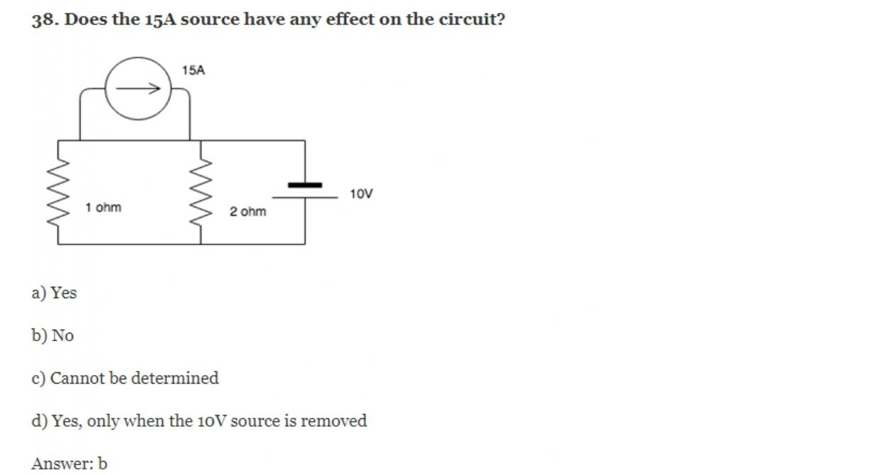
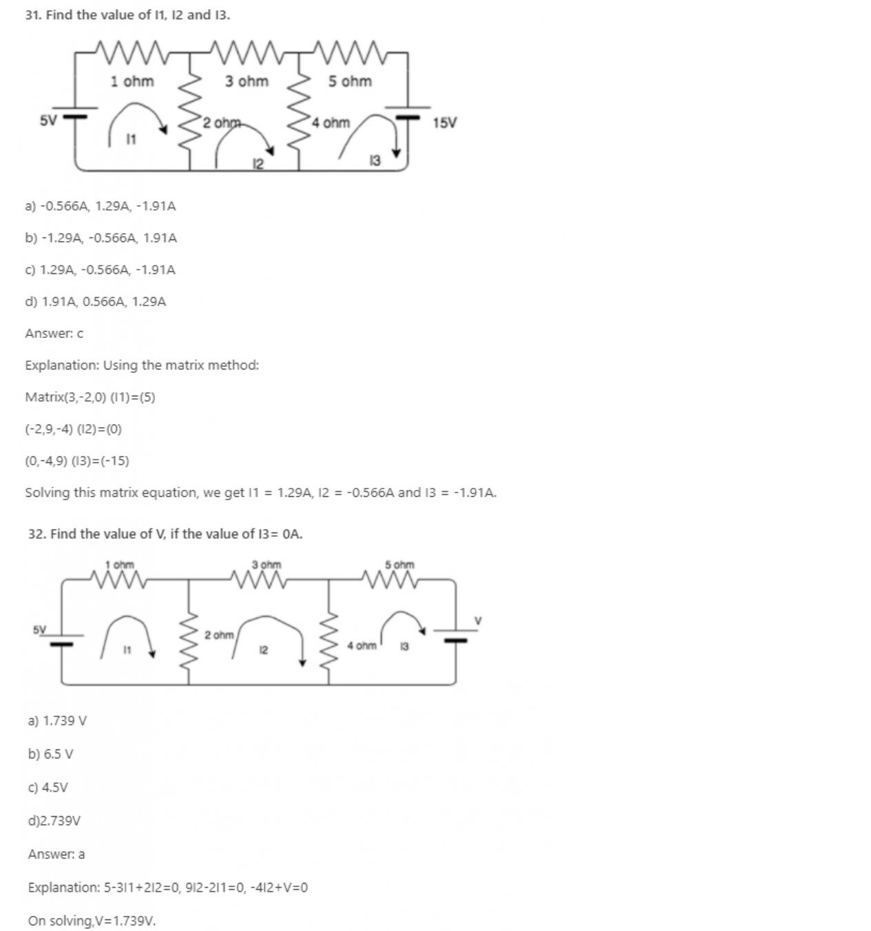
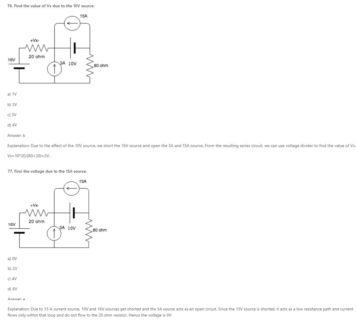
Explanation: The 15A current source has a lower resistance path associated with it and hence it keeps moving in that particular loop. It does not leave that loop and enter the circuit, hence the circuit is not affected by it.
39. KVL is associated with____________
a) Mesh analysis
b) Nodal analysis
c) Both mesh and nodal
d) Neither mesh nor nodal
Answer: a
Explanation: KVL employs mesh analysis to find the different mesh currents by finding the IR products in each mesh.
a) Mesh analysis
b) Nodal analysis
c) Both mesh and nodal
d) Neither mesh nor nodal
Answer: b
Explanation: KCL employs nodal analysis to find the different node voltages by finding the value if a current in each branch.
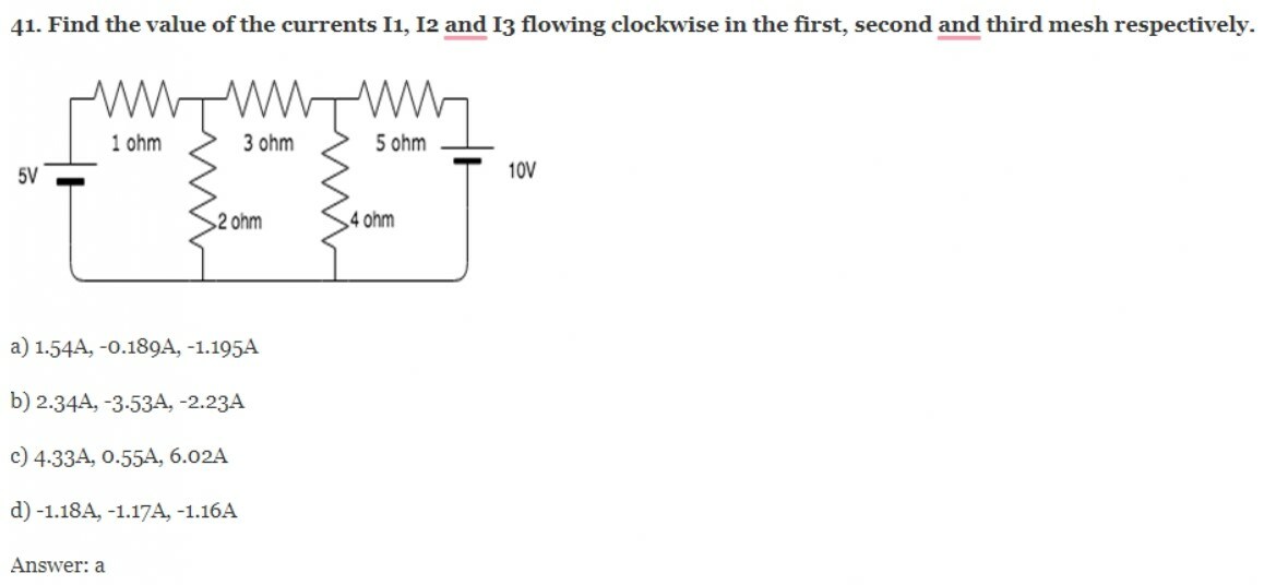
Explanation: The three mesh equations are:
-3I1+2I2-5=0
2I1-9I2+4I3=0
4I2-9I3-10=0
Solving the equations, we get I1= 1.54A, I2=-0.189 and I3= -1.195A.
48. Mesh analysis employs the method of ___________
a) KVL
b) KCL
c) Both KVL and KCL
d) Neither KVL nor KCL
Answer: a
Explanation: KVL employs mesh analysis to find the different mesh currents by finding the IR products in each mesh.
49. Mesh analysis is generally used to determine _________
a) Voltage
b) Current
c) Resistance
d) Power
Answer: b
Explanation: Mesh analysis uses Kirchhoff’s Voltage Law to find all the mesh currents. Hence it is a method used to determine current.
a) Planar circuits
b) Non-planar circuits
c) Both planar and non-planar circuits
d) Neither planar nor non-planar circuits
Answer: a
Explanation: If the circuit is not planar, the meshes are not clearly defined. In planar circuits, it is easy to draw the meshes hence the meshes are clearly defined.
56. Nodal analysis is generally used to determine_______
a) Voltage
b) Current
c) Resistance
d) Power
Answer: a
Explanation: Nodal analysis uses Kirchhoff’s Current Law to find all the node voltages. Hence it is a method used to determine the voltage.
a) 10
b) 9
c) 8
d) 7
Answer: b
Explanation: One node is taken as reference node so, the number of equations we get is always one less than the number of nodes in the circuit, hence for 10 nodes we get 9 equations.
58. Nodal analysis can be applied for________
a) Planar networks
b) Non-planar networks
c) Both planar and non-planar networks
d) Neither planar nor non-planar networks
Answer: c
Explanation: Nodal analysis can be applied for both planar and non-planar networks since each node, whether it is planar or non-planar, can be assigned a voltage.
59. How many nodes are taken as reference nodes in a nodal analysis?
a) 1
b) 2
c) 3
d) 4
Answer: a
Explanation: In the nodal analysis, one node is treated as the reference node and the voltage at that point is taken as 0.
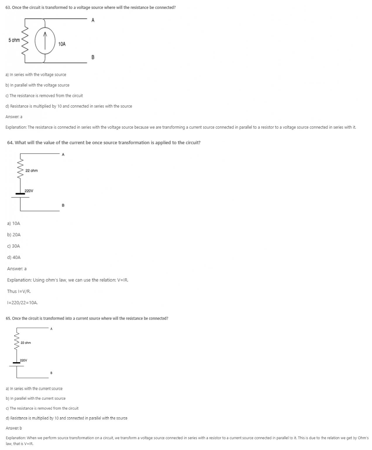
a) Current source in series with a resistor
b) Current source in parallel with a resistor
c) Voltage source in parallel with a resistor
d) Cannot be modified
Answer: b
Explanation: A voltage source connected in series can be converted to a current source connected in parallel using the relation obtained from Ohm’s law, that is V=IR. This equation shows that a voltage source connected in series has the same impact as a current source connected in parallel.

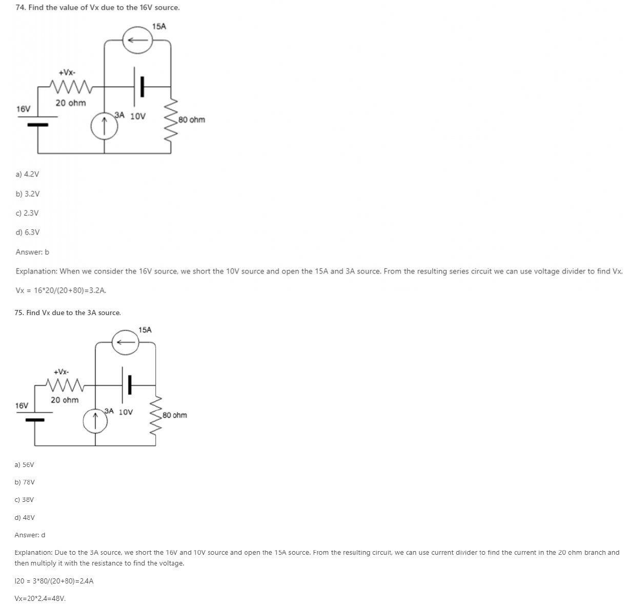
66. A current source connected in parallel with a resistor can be converted to a?
a) Current source in series with a resistor
b) Voltage source in series with a resistor
c) Voltage source in parallel with a resistor
d) Cannot be modified
Answer: b
Explanation: A current source connected in parallel can be converted to a voltage source connected in series using the relation obtained from Ohm’s law, that is V=IR. This equation shows that a current source connected in parallel has the same impact as a voltage source connected in series.
67. A source transformation is_________
a) Unilateral
b) Bilateral
c) Unique
d) Cannot be determined
Answer: b
Explanation: A source transformation is bilateral because a voltage source can be converted to a current source and vice-versa.
68. In source transformation________
a) Voltage source remains the same
b) Current sources remain the same
c) Both voltage and current source remain the same
d) Resistances remain the same
Answer: d
Explanation: In source transformation, the value of the voltage and current sources change when changed from voltage to current source and current to voltage source but the value of the resistance remains the same.
69. If there are 3 10V sources connected in parallel then on source transformation__________
a) The effect of all the sources is considered
b) The effect of only one source is considered
c) The effect of none of the sources is considered
d) The effect of only 2 sources is considered.
Answer: b
Explanation: When voltages are connected in parallel, the effect of only one source is considered because the effect of the voltage remains the same when connected in parallel.
a) Shorted
b) Opened
c) Removed
d) Undisturbed
Answer: a
Explanation: In superposition theorem when we consider the effect of one voltage source, all the other voltage sources are shorted and current sources are opened.
71.In superposition theorem, when we consider the effect of one current source, all the other voltage sources are ____________
a) Shorted
b) Opened
c) Removed
d) Undisturbed
72. In superposition theorem, when we consider the effect of one voltage source, all the other current sources are ____________
a) Shorted
b) Opened
c) Removed
d) Undisturbed
Answer: b
Explanation: In superposition theorem when we consider the effect of one voltage source, all the other current sources are opened and voltage sources are shorted.
73. In superposition theorem, when we consider the effect of one current source, all the other current sources are ____________
a) Shorted
b) Opened
c) Removed
d) Undisturbed
Answer: b
Explanation: In superposition theorem, whether we consider the effect of a voltage or current source, current sources are always opened and voltage sources are always shorted.
78. Superposition theorem is valid for _________
a) Linear systems
b) Non-linear systems
c) Both linear and non-linear systems
d) Neither linear nor non-linear systems
Answer: a
Explanation: Superposition theorem is valid only for linear systems because the effect of a single source cannot be individually calculated in a non-linear system.
a) Current
b) Voltage
c) Power
d) Works for all: current, voltage and power
Answer: c
Explanation: Power across an element is not equal to the power across it due to all the other sources in the system. The power in an element is the product of the total voltage and the total current in that element.
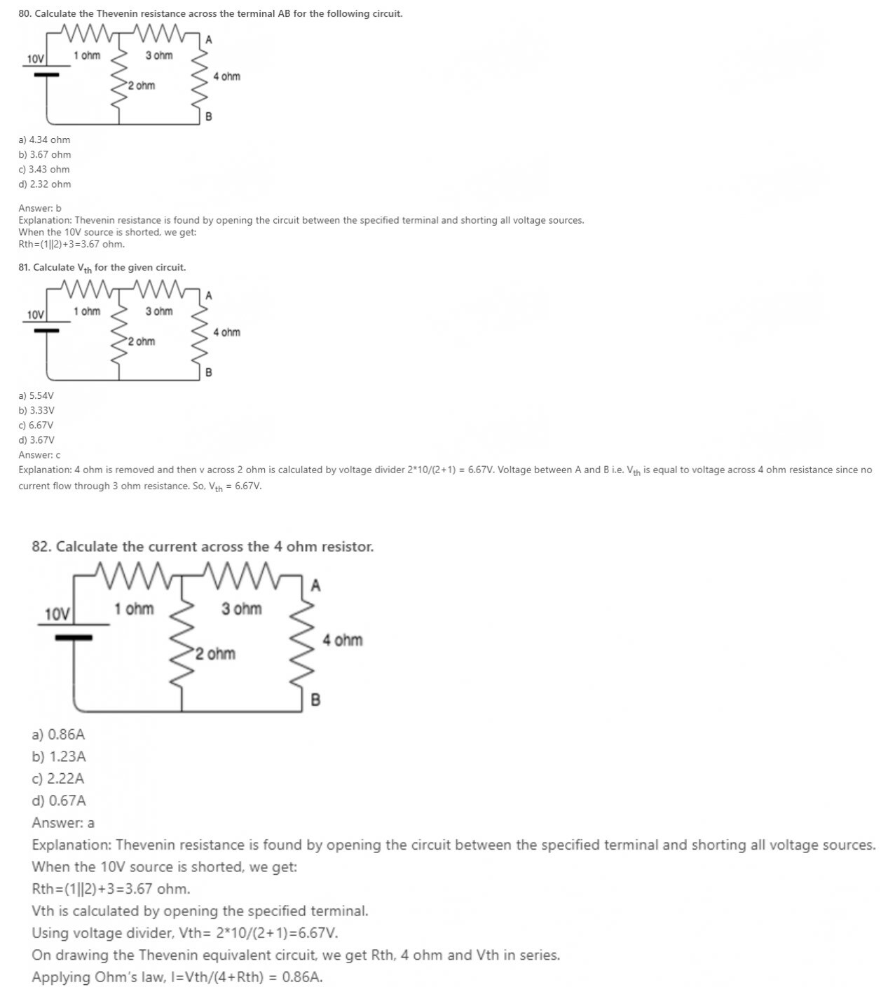
83. The Thevenin voltage is the__________
a) Open circuit voltage
b) Short circuit voltage
c) Open circuit and short circuit voltage
d) Neither open circuit nor short circuit voltage
Answer: a
Explanation: Thevenin voltage is obtained by opening the specified terminals so it is open circuit voltage. It is not the short circuit voltage because if specified terminals are shorted voltage is equal to zero.
84. Thevenin resistance is found by ________
a) Shorting all voltage sources
b) Opening all current sources
c) Shorting all voltage sources and opening all current sources
d) Opening all voltage sources and shorting all current sources
Answer: c
Explanation: Ideal current sources have infinite internal resistance hence behave like an open circuit whereas ideal voltage sources have zero internal resistance hence behave as a short circuit.
85. Thevenin’s theorem is true for __________
a) Linear networks
b) Non-Linear networks
c) Both linear networks and nonlinear networks
d) Neither linear networks nor non-linear networks
Answer: a
Explanation: Thevenin’s theorem works for only linear circuit elements and not non-linear ones such as BJT, semiconductors etc.
86. In Thevenin’s theorem Vth is __________
a) Sum of two voltage sources
b) A single voltage source
c) Infinite voltage sources
d) 0
Answer: b
Explanation: Thevenin’s theorem states that a combination of voltage sources, current sources and resistors is equivalent to a single voltage source V and a single series resistor R.
87. Vth is found across the ____________ terminals of the network.
a) Input
b) Output
c) Neither input nor output
d) Either input or output
Answer: b
Explanation: According to Thevenin’s theorem, Vth is found across the output terminals of a network and not the input terminals.
89. Can we use Thevenin’s theorem on a circuit containing a BJT?
a) Yes
b) No
c) Depends on the BJT
d) Insufficient data provided
Answer: b
Explanation: We can use Thevenin’s theorem only for linear networks. BJT is a non-linear network hence we cannot apply Thevenin’s theorem for it.
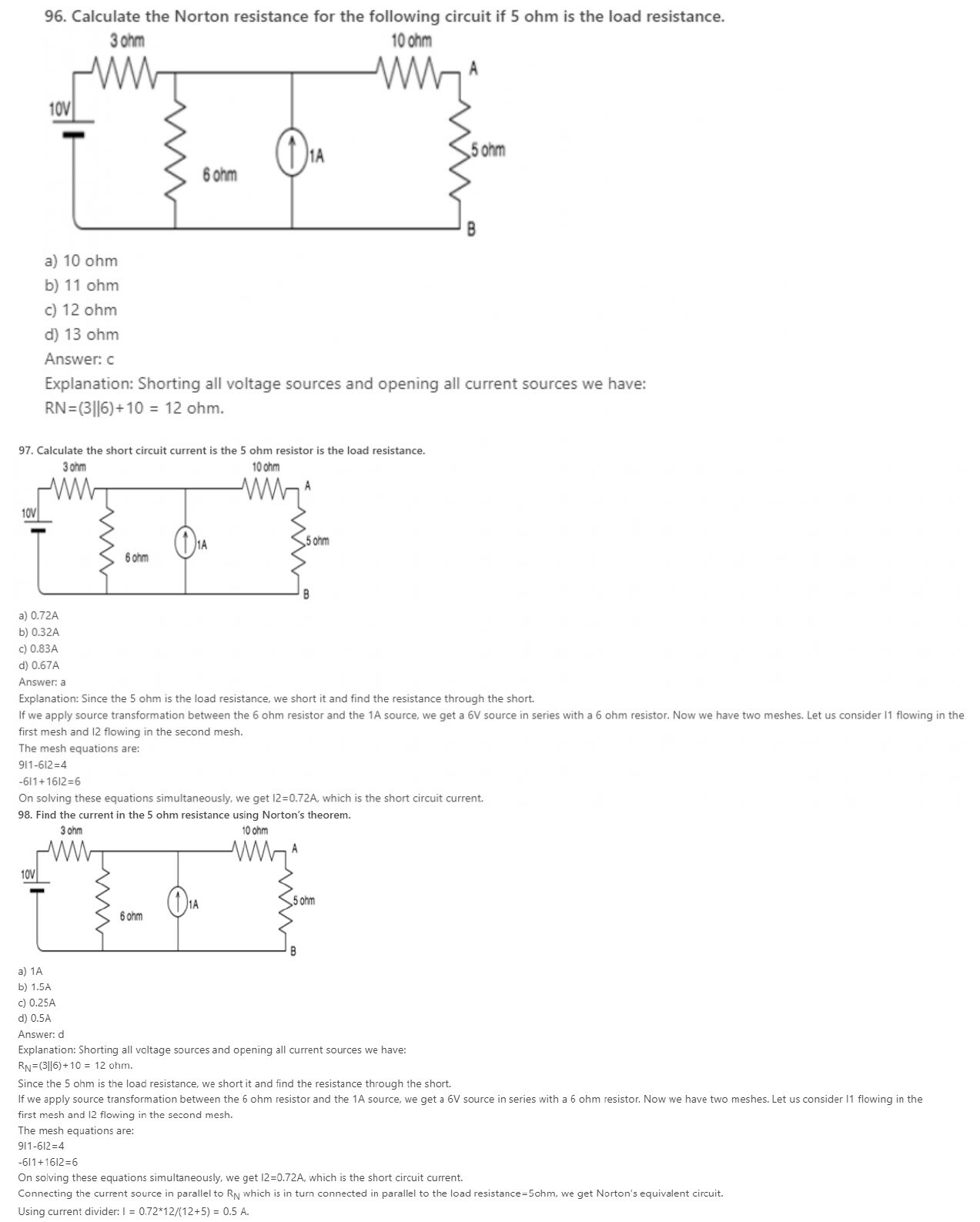
90. The Norton current is the_______
a) Short circuit current
b) Open circuit current
c) Open circuit and short circuit current
d) Neither open circuit nor short circuit current
Answer: a
Explanation: Norton current is obtained by shorting the specified terminals. So, it is the short circuit current. It is not the open circuit current because if specified terminals get open circuited then current is equal to zero.
92. Norton’s theorem is true for __________
a) Linear networks
b) Non-Linear networks
c) Both linear networks and nonlinear networks
d) Neither linear networks nor non-linear networks
Answer: a
Explanation: Norton’s theorem works for only linear circuit elements and not non-linear ones such as BJT, semiconductors etc.
93. In Norton’s theorem Isc is__________
a) Sum of two current sources
b) A single current source
c) Infinite current sources
d) 0
Answer: b
Explanation: Norton’s theorem states that a combination of voltage sources, current sources and resistors is equivalent to a single current source IN and a single parallel resistor RN.
94. Isc is found across the ____________ terminals of the network.
a) Input
b) Output
c) Neither input nor output
d) Either input or output
Answer: b
Explanation: According to Norton’s theorem, Isc is found through the output terminals of a network and not the input terminals.
95. Can we use Norton’s theorem on a circuit containing a BJT?
a) Yes
b) No
c) Depends on the BJT
d) Insufficient data provided
Answer: b
Explanation: We can use Norton’s theorem only for linear networks. BJT is a non-linear network hence we cannot apply Norton’s theorem for it.
99. Which of the following is also known as the dual of Norton’s theorem?
a) Thevenin’s theorem
b) Superposition theorem
c) Maximum power transfer theorem
d) Millman’s theorem
Answer: a
Explanation: Thevenin’s theorem is also known as the dual of Norton’s theorem because in Norton’s theorem we find short circuit current which is the dual of open circuit voltage-what we find in Thevenin’s theorem.
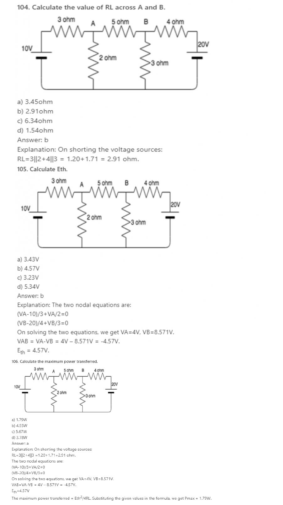
100. The maximum power drawn from source depends on __________
a) Value of source resistance
b) Value of load resistance
c) Both source and load resistance
d) Neither source or load resistance
Answer: b
Explanation: The maximum power transferred is equal to E2/4*RL. So, we can say maximum power depends on load resistance.
102. If source impedance is a complex number Z, then load impedance is equal to _________
a) Z’
b) -Z
c) -Z’
d) Z
Answer: a
Explanation: When Source impedance is equal to Z, its load impedance is the complex conjugate of Z which is Z’. Only under this condition, maximum power can be drawn from the circuit.
103. If ZL=Zs’, then RL=?
a) -RL
b) Rs
c) -Rs
d) 0
Answer: b
Explanation: Rs is the real part of the complex number ZL. Hence when we find the complex conjugate the real part remains the same whereas the complex part acquires a negative sign.
107. Does maximum power transfer imply maximum efficiency?
a) Yes
b) No
c) Sometimes
d) Cannot be determined
Answer: b
Explanation: Maximum power transfer does not imply maximum efficiency. If the load resistance is smaller than source resistance, the power dissipated at the load is reduced while most of the power is dissipated at the source then the efficiency becomes lower.
108. Under the condition of maximum power efficiency is?
a) 100%
b) 0%
c) 30%
d) 50%
Answer: d
Explanation: Efficiency=(Power output/ Power input)*100.
Power Output=I2RL, Power Input=I2(RL+RS)
Under maximum power transfer conditions, RL=RS
Power Output=I2RL; Power Input=2*I2RL
Thus efficiency=50%.
109. Name some devices where maximum power has to be transferred to the load rather than maximum efficiency.
a) Amplifiers
b) Communication circuits
c) Both amplifiers and communication circuits
d) Neither amplifiers nor communication circuits
Answer: c
Explanation: Maximum power transfer to the load is preferred over maximum efficiency in both amplifiers and communication circuits since in both these cases the output voltage is more than the input.
1. Find the average value of current when the current that are equidistant are 4A, 5A and 6A.
a) 5A
b) 6A
c) 15A
d) 10A
Answer: a
Explanation: The average value of current is the sum of all the currents divided by the number of currents. Therefore average current = (5+4+6)/3=5A.
2. What is the current found by finding the current in an equidistant region and dividing by n?
a) RMS current
b) Average current
c) Instantaneous current
d) Total current
Answer: b
Explanation: The average value of the current is the sum of all the currents divided by the number of currents.
3. RMS stands for ________
a) Root Mean Square
b) Root Mean Sum
c) Root Maximum sum
d) Root Minimum Sum
Answer: a
Explanation: RMS stands for Root Mean Square. This value of current is obtained by squaring all the current values, finding the average and then finding the square root.
4. What is the type of current obtained by finding the square of the currents and then finding their average and then fining the square root?
a) RMS current
b) Average current
c) Instantaneous current
d) Total current
Answer: a
Explanation: RMS stands for Root Mean Square. This value of current is obtained by squaring all the current values, finding the average and then finding the square root.
5. __________ current is found by dividing the area enclosed by the half cycle by the length of the base of the half cycle.
a) RMS current
b) Average current
c) Instantaneous current
d) Total current
Answer: b
Explanation: The average value of current is the sum of all the currents divided by the number of currents. Hence it can also be found by dividing the area enclosed by the half cycle by the length of the base of the half cycle.
6. What is the effective value of current?
a) RMS current
b) Average current
c) Instantaneous current
d) Total current
Answer: a
Explanation: RMS current is also known as the effective current. RMS stands for Root Mean Square. This value of current is obtained by squaring all the current values, finding the average and then finding the square root.
7. In a sinusoidal wave, average current is always _______ rms current.
a) Greater than
b) Less than
c) Equal to
d) Not related
Answer: b
Explanation: The average value of current is the sum of all the currents divided by the number of currents whereas RMS current is obtained by squaring all the current values, finding the average and then finding the square root. Hence RMS current is greater than average current.
8. For a rectangular wave, average current is ______ rms current.
a) Greater than
b) Less than
c) Equal to
d) Not relate
Answer: c
Explanation: The rms value is always greater than the average except for a rectangular wave, in which the heating effect remains constant so that the average and the rms values are the same.
9. Peak value divided by the rms value gives us?
a) Peak factor
b) Crest factor
c) Both peak and crest factor
d) Neither peak nor crest factor
Answer: c
Explanation: Peak and crest factor both mean the same thing. Hence the peak value divided by the rms value gives us the peak or crest factor.
10. Calculate the crest factor if the peak value of current is 10A and the rms value is 2A.
a) 5
b) 10
c) 5A
d) 10A
Answer: a
Explanation: We know that:
Crest factor = Peak value/RMS value.
Substituting the values from the given question, we get crest factor=5.
12. If Im is the maximum value of a sinusoidal voltage, what is the instantaneous value?
a) i=Im/2
b) i=Imsinθ
c) i=Imcosθ
d) i=Imsinθ or i=Imcosθ
Answer: d
Explanation: The instantaneous value of a sinusoidal varying current is i=Imsinθ or i=Imcosθ where Im is the maximum value of current.
13. Average value of current over a half cycle is?
a) 0.67Im
b) 0.33Im
c) 6.7Im
d) 3.3Im
Answer: a
Explanation: Average current = ∫0πidθ/π = ∫0πImsinθ dθ/π = 2Im/π =0.67 Im.
14. What is the correct expression for the rms value of current?
a) Irms=Im/2
b) Irms=Im/√2
c) Irms=Im/4
d) Irms=Im
Answer: b
Explanation: Irms2 = ∫0πdθ i2/2π = Im2/2
Irms=Im/√2.
15. Average value of current over a full cycle is?
a) 0.67Im
b) 0
c) 6.7Im
d) 3.3Im
Answer: b
Explanation: Average of sine or cosine over a period is zero so, average value of current over full cycle is zero.
16. What is the correct expression for the form factor?
a) Irms * Iav
b) Irms / Iav
c) Irms + Iav
d) Irms – Iav
Answer: b
Explanation: The correct expression for form factor is Irms/Iav where Irms is the rms value of the current and Iav is the average current.
17. For a direct current, the rms current is ________ the mean current.
a) Greater than
b) Less than
c) Equal to
d) Not related to
Answer: c
Explanation: For a direct current, the mean current value is the same as that of the rms current.
19. What is the value of the form factor for sinusoidal current?
a) π/2
b) π/4
c) 2π
d) π/√2
Answer: a
Explanation: For sinusoidal current, Irms=Im/√2
Iav=√2 Im/π
So, form factor = Irms/Iav = π/2.
20. If the maximum value of the current is 5√2 A, what will be the value of the average current?
a) 10/π A
b) 5/π A
c) 15/π A
d) 25/π A
Answer: a
Explanation: We know, the value of the average current = value of max current *√2 /π
Substituting the value of max current we get, rms current = 10/π A.
22. What is impedance at resonance?
a) maximum
b) minimum
c) zero
d) cannot be determined
Answer: b
Explanation: At resonance, XL=XC
Z2=R2+(XL-XC)2
Z=R So Z is minimum at resonance.
23. What is the value of impedance at resonance?
a) XL
b) XC
c) R
d) 0
Answer: c
Explanation: At resonance, XL=XC
Z2=R2+(XL-XC)2
Z=R So Z is minimum at resonance.
24. What is φ in terms of voltage?
a) φ=cos-1V/VR
b) φ=cos-1V*VR
c) φ=cos-1VR/V
d) φ=tan-1V/VR
Answer: c
Explanation: Form the voltage triangle, we get cosφ= VR/V.
Hence φ=cos-1VR/V.
25. What is tanϕ for RC circuit?
a) XC/R
b) XL/R
c) R/Z
d) Z/R
Answer: a
Explanation: From the impedance triangle, height gives capacitive reactance and base gives resistance.
tanϕ=XC/R.
26. What is the resonance condition?
a) When XL>XC
b) When XL<XC
c) When XL=XC
d) When XC=infinity
Answer: c
Explanation: The current is in phase with the voltage when the capacitive reactance is in equal to the inductive reactance. This is known as resonance condition.
27. What is the frequency in resonance condition?
a) Minimum
b) Maximum
c) Cannot be determined
d) Zero
Answer: b
Explanation: At resonance condition, the frequency is maximum since the inductive reactance is equal to the capacitive reactance. XL=XC.
28. A resistance of 7 ohm is connected in series with an inductance of 31.8mH. The circuit is connected to a 100V 50Hz sinusoidal supply. Calculate the current in the circuit.
a) 2.2A
b) 4.2A
c) 6.2A
d) 8.2A
Answer: d
Explanation: XL=2*π*f*L = 10 ohm. Z2=(R2+XL2)
Therefore the total impedance Z = 12.2ohm.
V=IZ, therefore I=V/Z=100/12.2 = 8.2A.
29. A resistance of 7 ohm is connected in series with an inductance of 31.8mH. The circuit is connected to a 100V 50Hz sinusoidal supply. Calculate the phase difference.
a) -55.1
b) 55.1
c) 66.1
d) -66.1
Answer: a
Explanation: φ=tan-1(XL/R)=55.1
Since this is an inductive circuit, the current will lag, hence φ= -55.1.
30. A resistance of 7 ohm is connected in series with an inductance of 31.8mH. The circuit is connected to a 100V 50Hz sinusoidal supply. Calculate the voltage across the resistor.
a) 31.8V
b) 57.4V
c) 67.3V
d) 78.2V
Answer: b
Explanation: XL=2*π*f*L = 10 ohm. Z2=(R2+XL2)
Therefore, the total impedance Z = 12.2ohm.
V=IZ, therefore I=V/Z=100/12.2 = 8.2A. Voltage across resistor = 8.2*7 = 57.4V.
32. A resistance of 7 ohm is connected in series with an inductance of 31.8mH. The circuit is connected to a x V 50Hz sinusoidal supply. The current in the circuit is 8.2A. Calculate the value of x.
a) 10V
b) 50V
c) 100V
d) 120V
Answer: c
Explanation: XL=2*π*f*L= 10 ohm. Z2=(R2+XL2)
Therefore, the total impedance Z = 12.2ohm.
V=IZ, therefore V = 12.2*8.2 = 100V.
33. Which, among the following, is the correct expression for φ.
a) φ=tan-1 (XL/R)
b) φ=tan-1 (R/XL)
c) φ=tan-1 (XL*R)
d) φ=cos-1 (XL/R)
Answer: a
Explanation: From the impedance triangle, we get tanφ= XL/R.
Hence φ=tan-1 (XL/R).
34. For an RL circuit, the phase angle is always ________
a) Positive
b) Negative
c) 0
d) 90
Answer: b
Explanation: For a series resistance and inductance circuit the phase angle is always a negative value because the current will always lag the voltage.
35. What is φ in terms of voltage?
a) φ=cos-1V/VR
b) φ=cos-1V*VR
c) φ=cos-1VR/V
d) φ=tan-1V/VR
Answer: c
Explanation: From the voltage triangle, we get cosφ= VR/V.
Hence φ=cos-1VR/V.
36. What is sinϕ from impedance triangle?
a) XL/R
b) XL/Z
c) R/Z
d) Z/R
Answer: b
Explanation: In the Impedance triangle, Base is R, Hypotenuse is Z, Height is XL.
So, sinϕ = XL/Z.
1. In a balanced three-phase system-delta load, if we assume the line voltage is VRY = V∠0⁰ as a reference phasor. Then the source voltage VYB is?
a) V∠0⁰
b) V∠-120⁰
c) V∠120⁰
d) V∠240⁰
2. In the question 1, the source voltage VBR is?
a) V∠120⁰
b) V∠240⁰
c) V∠-240⁰
d) V∠-120⁰
3. In a delta-connected load, the relation between line voltage and the phase voltage is?
a) line voltage > phase voltage
b) line voltage < phase voltage
c) line voltage = phase voltage
d) line voltage >= phase voltage
4. If the load impedance is Z∠Ø, the current (IR ) is?
a) (V/Z)∠-Ø
b) (V/Z)∠Ø
c) (V/Z)∠90-Ø
d) (V/Z)∠-90+Ø
5. In the question 4, the expression obtained for current (IY) is?
a) (V/Z)∠-120+Ø
b) (V/Z)∠120-Ø
c) (V/Z)∠120+Ø
d) (V/Z)∠-120-Ø
6. In the question 4, the expression obtained for current (IB) is?
a) (V/Z)∠-240+Ø
b) (V/Z)∠-240-Ø
c) (V/Z)∠240-Ø
d) (V/Z)∠240+Ø
7. A three phase, balanced delta connected load of (4+j8) Ω is connected across a 400V, 3 – Ø balanced supply. Determine the phase current IR . Assume the phase sequence to be RYB.
a) 44.74∠-63.4⁰A
b) 44.74∠63.4⁰A
c) 45.74∠-63.4⁰A
d) 45.74∠63.4⁰A
8. In the question 7, determine the phase current IY.
a) 44.74∠183.4⁰A
b) 45.74∠183.4⁰A
c) 44.74∠183.4⁰A
d) 45.74∠-183.4⁰A
9. In the question 7, determine the phase current IB.
a) 44.74∠303.4⁰A
b) 44.74∠-303.4⁰A
c) 45.74∠303.4⁰A
d) 45.74∠-303.4⁰A
10. Determine the power (kW) drawn by the load.
a) 21
b) 22
c) 23
d) 24
a) Go quickly to 100 ohms and remain there
b) Show low resistance momentarily and back off to a very high resistance
c) Not move at all
d) Show very high resistance first and then low
Answer: (b)
12. Which of the following error may arise in wattmeter if it is not compensated for the errors?
a) Voltage coil inductance
b) Voltage coil capacitance
c) Eddy currents
d) (a), (b) and (c)
Answer: (d)
13. Which of the following is methods is the commonest method of measuring three balanced or unbalanced power?
a) One wattmeter method
b) Two wattmeter method
c) Three wattmeter method
d) Ammeter method
Answer: (b)
14. One-Wattmeter method is used to measure
a) The power when load is balance in three phase circuit
b) The power when load is unbalanced in three phase circuit
c) (a) or (b)
d) Single phase power with balanced load
Answer: (a)
15. The reactive power can be measured with wattmeter when voltage across voltage coil is adjusted to be out of phase with the current by
a) 90°
b) 180°
c) 45°
d) 0°
e) 120°
Answer: (a)
16.The change of frequency affects the circuit parameters of wattmeter connected to measure power of three-phase AC system
a) True
b) False
Answer: (b)
17. Which of the following devices are required to measure three phase balance power?
a) One wattmeter
b) One wattmeter and one voltage transformer of 1:1 ratio
c) One wattmeter and two current transformers of 1:1 ratio
d) Either (b) or (c)
Answer: (d)
18. The total power P measured in Y star three-phase circuit is given by
a) P = 3VI cos ϕ
b) P = √I cos ϕ
c) P = √3VI cos ϕ
d) P = √2VI cos ϕ
Answer: (c)
Where V and I are the line voltage and line current respectively.
19.In the above question, the power in delta three-phase circuit is given by
a) P = 3 VI cos ϕ
b) P = √3 VI cos ϕ
c) P = √2 VI cos ϕ
d) P = √3 VI sin ϕ
Answer: (b)
20. The dynamometer wattmeter can be used to measure
a) AC power only
b) DC power only
c) AC or DC power
d) AC power of single-phase circuits
Answer: (c)
1. How many design principles are present in the current transformers?
a) 2
b) 3
c) 4
d) 5
2. What should be done in order to reduce the errors in the core?
a) armature mmf is to kept low
b) field mmf to be kept high
c) the exciting mmf is to be kept low
d) the field mmf is to be kept high
3. How many classifications are the magnetic alloys used in the current transformers classified into?
a) 3
b) 2
c) 4
d) 5
4. What is the material used in the transformer when the transformer errors should be small?
a) mumetal cores
b) steel cores
c) permender cores
d) presshamn cores
5. What is the relation of the secondary winding leakage reactance and secondary circuit impedance?
a) secondary winding leakage reactance is directly proportional to the secondary circuit impedance
b) secondary winding leakage reactance is indirectly proportional to the secondary circuit impedance
c) secondary winding leakage reactance is directly proportional to the square of the secondary circuit impedance
d) secondary winding leakage reactance is indirectly proportional to the square of the secondary circuit impedance
6. The ring shaped cores are made use of in the reduction of the secondary winding leakage reactance and secondary impedance.
a) true
b) false
7. What type of core is employed when the performance standard required is not so high?
a) rectangular strips
b) c-shaped sections
c) rectangular strips or c-shaped sections
d) rectangular strips and c-shaped sections
8. What should the magnetic path be in order to reduce the core reluctance?
a) length of the magnetic path in core should be low
b) length of the magnetic path in core should be medium
c) length of the magnetic path in core should be high
d) length of the magnetic path in core should be very high
9. What is the value of the rated secondary current?
a) 1 A
b) 2 A
c) 3 A
d) 5 A
10. What are the disadvantages of the low rated secondary current transformer?
a) high cost
b) high voltages
c) high voltages or high cost
d) high voltages and high cost
12. What is the rating of the primary current in the current transformer?
a) 200 A
b) 300 A
c) 400 A
d) 500 A
13. How many types are the current transformers classified into?
a) 2
b) 3
c) 4
d) 5
14. What is the wound type current transformer?
a) primary winding having one full turn wound on core
b) primary winding having more than one full turn wound on core
c) secondary winding having one full turn wound on core
d) secondary winding having more than one full turn wound on core
15. What is the bar type current transformer?
a) primary winding consists of a rod of suitable size and material
b) primary winding consists of a bar of suitable size and material
c) secondary winding consists of a rod of suitable size and material
d) secondary winding consists of a bar of suitable size and material
16. How many commonly used shapes of current transformer are present?
a) 1
b) 2
c) 3
d) 4
17. What material is made use of for the lamination in the current transformer?
a) cold rolled steels
b) hot rolled steels
c) copper
d) hot iron
18. What is the insulation material used in the current transformer?
a) elephantide
b) presspahn
c) elephantide and presspahn
d) elephantide or presspahn
19. What is the additional usage of the presspahn material used as insulation material?
a) lamination
b) to reduce the losses
c) to protect secondary winding conductor from mechanical damage
d) to protect secondary winding conductor from electrical damage
21. How many faces are present in the split core current transformer?
a) 2
b) 3
c) 4
d) 5
22. The current transformers are assembled on to the secondary conductors “on site” for either permanent or temporary duty.
a) true
b) false
23. What is the insulation material on the primary conductor?
a) bakelized paper tube
b) resin
c) bakelized paper tube and resin
d) bakelized paper tube or resin
24. How is the reluctance of the interleaved corner related with the magnetizing current?
a) reluctance of the interleaved corner is directly proportional to the magnetizing current
b) reluctance of the interleaved corner is indirectly proportional to the magnetizing current
c) reluctance of the interleaved corner is directly proportional to the square of the magnetizing current
d) reluctance of the interleaved corner is indirectly proportional to the square of the magnetizing current
25. To reduce the peak voltage between layers, the secondary winding is being sectionalized.
a) true
b) false
27. What is the formula of the actual ratio?
a) actual ratio = turns ratio + load current * secondary current
b) actual ratio = turns ratio * load current * secondary current
c) actual ratio = turns ratio + load current / secondary current
d) actual ratio = turns ratio / load current * secondary current
28. What happens if the number of secondary turns is reduced?
a) the primary turns is reduced
b) the output is reduced
c) the efficiency is reduced
d) the transformation ratio is reduced
29. What is the best number of secondary turns of the current transformer?
a) 1
b) 2
c) 1 or 2 less than the number such that the turns ratio is equal to the nominal current ratio
d) 1 or 2 more than the number such that the turns ratio is equal to the nominal current ratio
30. The phase angle error is significantly affected by the small change in secondary turns.
a) true
b) false
View Answer
32. What is the range of current density in the windings of the current transformer?
a) 1-3 A per mm2
b) 2-3 A per mm2
c) 1-2 A per mm2
d) 0.5-2 A per mm2
33. How many factors are present in the behavior of transformer under short circuit conditions?
a) 2
b) 3
c) 4
d) 5
34. What is the definition of current transformer?
a) it is used for measuring high voltage
b) it is used for measuring low voltage
c) it is used for measuring high current
d) it is used for measuring low current
35. How many classifications are present for the current transformers?
a) 1
b) 2
c) 3
d) 4
36. What is the definition of the ideal current transformer?
a) the primary and secondary windings are in exact ratio and same phase relationship
b) the primary winding and secondary winding ratio is greater than 1 and same phase relationship
c) the primary and secondary winding ratio is lesser than 1 are in exact ratio and different phase relationship
d) the primary and secondary windings ratio is greater than 1 and different phase relationship
37. How many types of errors are present in the current transformers?
a) 1
b) 2
c) 3
d) 4
39. What is the formula of the angle between secondary induced voltage and secondary current?
a) phase angle = tan-1 *[(reactance of the secondary winding – reactance of the external burden) / (resistance of the secondary winding + resistance of the external burden)]
b) phase angle = tan-1 *[(reactance of the secondary winding – reactance of the external burden) / (resistance of the secondary winding – resistance of the external burden)]
c) phase angle = tan-1 *[(reactance of the secondary winding * reactance of the external burden) / (resistance of the secondary winding + resistance of the external burden)]
d) phase angle = tan-1 *[(reactance of the secondary winding + reactance of the external burden) / (resistance of the secondary winding + resistance of the external burden)]
40. What is the formula of the phase angle of the secondary load circuit?
a) phase angle of secondary load circuit = tan-1 * (reactance of the external burden/resistance of the external burden)
b) phase angle of secondary load circuit = tan-1 * (reactance of the external burden + resistance of the external burden)
c) phase angle of secondary load circuit = tan-1 * (reactance of the external burden – resistance of the external burden)
d) phase angle of secondary load circuit = tan-1 * (reactance of the external burden * resistance of the external burden)
41. What is the formula of the ratio error in the current transformers?
a) ratio error = turns ratio – regulation / regulation
b) ratio error = turns ratio + regulation / regulation
c) ratio error = turns ratio * regulation / regulation
d) ratio error = 1 / turns ratio * regulation
42. The ratio of active conductor section to total conductor section is called space factor.
a) true
b) false
1. A three-phase slip ring induction motor is fed from the rotor side with the stator winding short-circuited. The frequency of the current flowing in the short-circuited stator is ____________
a) Slip frequency
b) Supply frequency
c) The frequency corresponding to rotor speed
d) Zero
2. An 8-pole, 3-phase, 50 Hz induction motor is operating at a speed of 720 rpm. The frequency of the rotor current of the motor in Hz is __________
a) 2
b) 4
c) 3
d) 1
3. Calculate the phase angle of the sinusoidal waveform z(t)=78sin(456πt+2π÷78).
a) π÷39
b) 2π÷5
c) π÷74
d) 2π÷4
4. Calculate the moment of inertia of the disc having a mass of 54 kg and diameter of 91 cm.
a) 5.512 kgm2
b) 5.589 kgm2
c) 5.487 kgm2
d) 5.018 kgm2
5. Calculate the moment of inertia of the thin spherical shell having a mass of 73 kg and diameter of 36 cm.
a) 1.56 kgm2
b) 1.47 kgm2
c) 1.38 kgm2
d) 1.48 kgm2
6. A 50 Hz, 4poles, a single phase induction motor is rotating in the clockwise direction at a speed of 1425 rpm. The slip of motor in the direction of rotation & opposite direction of the motor will be respectively.
a) 0.05, 0.95
b) 0.04, 1.96
c) 0.05, 1.95
d) 0.05, 0.02
7. The frame of an induction motor is made of _________
a) Aluminum
b) Silicon steel
c) Cast iron
d) Stainless steel
8. The slope of the V-I curve is 5°. Calculate the value of resistance. Assume the relationship between voltage and current is a straight line.
a) .3254 Ω
b) .3608 Ω
c) .3543 Ω
d) .3443 Ω
9. In an induction motor, when the number of stator slots is equal to an integral number of rotor slots _________
a) There may be a discontinuity in torque slip characteristics
b) A high starting torque will be available
c) The maximum torque will be high
d) The machine may fail to start
10. A 3-phase induction motor runs at almost 1000 rpm at no load and 950 rpm at full load when supplied with power from a 50 Hz, 3-phase supply. What is the corresponding speed of the rotor field with respect to the rotor?
a) 30 revolution per minute
b) 40 revolution per minute
c) 60 revolution per minute
d) 50 revolution per minute
12. Calculate the active power in a 788 ω resistor with 178 A current flowing through it.
a) 24.96 MW
b) 24.44 MW
c) 24.12 MW
d) 26.18 MW
13. What is the special feature of single phase induction motor?
a) high starting torque
b) low starting torque
c) average starting torque
d) zero starting torque
14. How many methods are present in the self starting of the single phase induction motor?
a) 1
b) 2
c) 3
d) 4
15. What are the names of the windings used in the split phase starting?
a) starting windings
b) auxiliary windings
c) starting or auxiliary windings
d) starting and auxiliary windings
16. What is the displacement of the running and the starting windings used?
a) running winding displaces the starting winding by 180°
b) running winding displaces the starting winding by 90°
c) starting winding displaces the running winding by 90°
d) starting winding displaces the running winding by 180°
17. How is the required phase displacement between the current in the running and starting windings obtained?
a) by connecting a suitable resistor
b) by connecting a suitable capacitor
c) by connecting a suitable inductor
d) by connecting a suitable impedance
18. When is the starting winding cut out of the circuit in the split phase motor?
a) when the motor speed reaches 65 % of the full load speed
b) when the motor speed reaches 75 % of the full load speed
c) when the motor speed reaches 50 % of the full load speed
d) when the motor speed reaches 85 % of the full load speed
19. What is the shaded pole starting method?
a) part of the pole is shaded by open circuited copper ring
b) part of the pole is shaded by short circuited copper ring
c) the pole is shaded by open circuited copper ring
d) the pole is shaded by short circuited copper ring
20. What happens in the shaded pole starting method according to the displacement?
a) displacement between shaded and unshaded portion varies between 20°-25°
b) displacement between shaded and unshaded portion varies between 20°-35°
c) displacement between shaded and unshaded portion varies between 20°-30°
d) displacement between shaded and unshaded portion varies between 30°-45°
22. When is the repulsion motor starting method used?
a) when low starting torque is required
b) when high starting torque is required
c) when high running torque is required
d) when low running torque is required
23. What is the specialty in the repulsion motor starting method?
a) cage winding is replaced by armature windings
b) cage winding is replaced by field windings
c) cage winding is replaced by commutator windings
d) cage winding is replaced by bearings
24. What happens in the repulsion motor starting method?
a) the cage windings is dominant
b) the commutator windings are dominant
c) the rotor windings are dominant
d) the stator windings are dominant
25. What is the range of output watt for the shaded pole induction machine?
a) 0.37-50
b) 90-750
c) 90-3700
d) 7.5-370
26. What is the range of the starting current of capacitor type induction motor?
a) 5-7
b) 4–6
c) 2-6
d) 2-3
27. What is the range of the starting torque of shaded pole induction motor?
a) 2-4
b) 2-3.5
c) 0.2-0.3
d) 0.25-0.5
1.  In a split phase motor, the running winding should have
a.High resistance and low inductance
b.High resistance and High inductance
c.Low resistance and high inductance
d.Low resistance and Low inductance
Answer 3. Low resistance and high inductance
Explanation:
2. If the capacitor of a single-phase motor is short-circuited
a.The motor will not start
b.The motor will run in the same direction at reduced speed
c.The motor will run in reverse direction
d.None of the above
Answer 1. The motor will not start
Explanation:
When the capacitor is short-circuited high inrush current will flow in the winding which may burn the starting winding of a single phase induction motor.
 3. In a split phase motor
a.Both starting and running windings are connected through a centrifugal switch
b.Centrifugal switch is used to control supply voltage
c.The running winding is connected through a centrifugal switch
d.The starting winding is connected through a centrifugal switch
Answer 4. The starting winding is connected through a centrifugal switch Explanation:In split phase motor, the starting or auxiliary winding is connected through the centrifugal switch the purpose of the switch is to disconnect the starting winding of the motor once the motor approaches its normal operating speed.5. In a capacitor start and run motors the function of the running capacitor in series with the auxiliary winding is to a.Improve power factor b.Reduce fluctuations in torque c.Increase overload capacity d.To improve torque
Answer 1. Improve Power Factor
Explanation:
6. Which of the following motor will have relatively higher power factor?
a.Capacitor start motor
b.Shaded pole motor
c.Capacitor run motor
d.Split phase motor
Answer 3. Capacitor run motor
Explanation:
In capacitor run motor the starting winding remains connected all the times. There is no centrifugal switch in the capacitor run motor.
Because the capacitor remains in the circuit all the time a lower value capacitor is used the lower value capacitor has more phase shift as compared to the high-value capacitor, therefore, winding current is low.
Therefore the capacitor run motor has high running torque and improved power factor.
7. A centrifugal switch is used to disconnect ‘starting winding when motor has
a.Picked up 10% speed
b.Picked up 20% speed
c.Picked up 5 – 10% speed
d.Picked up 50 – 70% speed
26. How many steps are involved in the construction of a single-phase induction motor?
a) 3
b) 4
c) 5
d) 6
27. What is the lamination used for the stator?
a) cast iron
b) die cast aluminium alloy frame
c) cast iron or die-cast aluminium alloy frame
d) cast iron and die-cast aluminium alloy frame
28. What type of coils are used for winding the single-phase induction motor generally?
a) rectangular coils
b) square coils
c) cruciform coils
d) circular coils
29. How many kinds of single phase windings are present?
a) 2
b) 3
c) 4
d) 5
30. How are the poles and pitches in the concentric windings?
a) single pole, different pitches
b) different pole, different pitches
c) different pole, single pitch
d) single pole, single pitch
32. When is the skein winding made use of?
a) when small amount of relatively small size wire is used
b) when large amount of relatively small size wire is used
c) when large amount of relatively large size wire is used
d) when small amount of relatively large size wire is used
32. What kind of motor employs the skein winding made use of?
a) maximum horse power single phase induction motor
b) fractional horse power single phase induction motor
c) minimum horse power single phase induction motor
d) zero horse power single phase induction motor
33. Which winding is mostly used winding in the single phase induction motor?
a) circular winding
b) concentric winding
c) progressive winding
d) skein winding
35. What is/are the advantages of the skein winding?
a) low cost to wind
b) low cost to insert
c) permits some freedom of choice of distribution
d) low cost to wind, low cost to insert, permits some freedom of choice of distribution
37. What material is used in the tunnel of the rotor of the single phase induction motor?
a) aluminium
b) copper
c) steel
d) wood
38. What type of operations are used in the starting switches?
a) mechanical operation
b) electrical operation
c) centrifugal operation and mechanical operation
d) centrifugal operation
39. The ac electrolytic capacitor is formed by winding two sheets of etched aluminium foil.
a) true
b) false
40. The electrolytic capacitor and insulator unit is impregnated using ethylene glycol or a derivative.
a) true
b) false
41. What is the range of the power factor of electrolytic capacitors?
a) 2-4
b) 4-6
c) 6-8
d) 7-9
Prepare For Your Placements: https://lastmomenttuitions.com/courses/placement-preparation/
![]()
/ Youtube Channel: https://www.youtube.com/channel/UCGFNZxMqKLsqWERX_N2f08Q
Follow For Latest Updates, Study Tips & More Content!
Not a member yet? Register now
Are you a member? Login now