Get Latest Exam Updates, Free Study materials and Tips

Engineering Drawing Viva Questions

Introduction to Engineering Graphics

Q1. Define Engineering Drawing. Why Drawing is called the Universal Language of Engineers?
Answer :

  • Engineering drawing is a graphical language of an engineer to convey one’s ideas most effectively, easily, conveniently and with high speed.
  • So Engineering drawing is a starting point of all engineering branches such as Mechanical, Production, Civil, Electrical, Electronics, Computer science, Chemical etc. 
  • It is spoken, read, and written in its own way. Engineering drawing has its own grammar in terms of projections, conventional representations, types of lines, abbreviations, symbols and various geometric constructions.

Q2. Name Different Drawing Instruments.? 

Ans –Drawing board, drawing sheet, mini-drafter, scale, pencil and sandpaper block, cello-tape, eraser and compass

Q3. What are Different Types of Scales?

Ans- Different styles of scales are:

  • Plain scale: In which, one can measure certain units and their one-tenth value. For example, a scale in cm and mm is a plain scale, and dm is another plain scale.
  • Diagonal scale:  In which one can measure certain units, its one-tenth value as well as its one-hundredth value. For example, a scale in m, dm and em is a diagonal scale, dm, and cm and mun is another diagonal scale.
  • Comparative or Corresponding scale:  These are two different scales having the same R.F. but different units. These can be placed side by side or placed over one and another, For example in alles and kilometres 
    • These scales can be plain scales or diagonal scales.
  • Vernier scale: It is a scale that is extremely accurate for measurement. It uses a Vernier calliper. Vernier calliper is an instrument to measure a dimension very precisely. Normally its least count is 1/100 of the scale unit. Saya scale is in em, then a Vernier can measure very accurately up to 1/100 of a cm

Q4. What are Applications Of Scales?

Ans-Scales can be used for the following purposes:

  • To draw an object on a full, reduced and enlarged scale.
  • To measure distances.
  • To mark dimensions on the drawing

Q5. What Are The Requirements For The Construction Of A Scale?
Answer :(i) Maximum distance to be measured
(ii) R.F.( representative fraction) of the scale
Units of scale i.e. mm, cm, m, km

Q6. Name The Different Types Of Line Use In Engg. Drawing?

  1.  Ans-  0.2 Mm Medium- Outlines, Dotted Lines, Cutting Plane Lines 
  2.  0.1 Mm Thin – Centre Lines, Section Lines, Dimension Lines, Extension Lines, Construction Lines, Leader Lines, Short Break Lines And Long Break Lines.

Q7. What Are Standard Specifications Of Drawing Sheets And Pencils?
 Ans- A0, A1, A2, A3, A4
H, 2H, 3H, 4H etc 
B, 2B, 3B, 4B etc

Q8.What do you Mean by R.F.? What is The Unit of R.F.?
 Ans: – The Ratio of length of the drawing to the actual length of the object is called The Representative Fraction (R.F). 
R.F. = Drawing Length / Actual Length 
R.F is unitless.

Q9. What Do You Mean By Convention/ Code?
Ans: The representation of any matter by some standard sign or symbol on the drawing is known as convention or code. The conventions make the drawing simple and easy to draw.

Engineering Curves

Q1. What are conic sections and why are they called so? 
Ans.  Ellipse, parabola and hyperbola are called conic sections because these curves appear on the surface of the cone when it is cut by some typical cutting planes.

Q2. Define Ellipse?
Ans:

  • It is the locus of a point moving in a plane in such a way that the ratio of its distance from a fixed point to its distance from a fixed line always remains constant and is less than one.
  • It is the locus of a point moving in a plane in such a way that the sum of its distance from two fixed points ( called foci ) always remains constant and is equal to the major axis of the ellipse.

Q3.Name the Method to draw an ellipse?
Ans

  •  General method 
  • Arc of the circle method 
  • Rectangle method 
  • Concentric Circle Method

Q4. Define Parabola? 

Ans. It is the locus of a point moving in a plane is such a way that the ratio of its distance from a fixed point is always equal to its distance from a fixed line. In other word its eccentricity is equal to one.

Q5. Name the Method to draw a Parabola ?
Ans

  1. General method 
  2. Rectangle method 
  3. Tangent or Triangle Method

Q6. Define hyperbola?
Ans

  •  It is the locus of a point moving in a plane is such a way that the ratio of its distance from a fixed point to its distance from a fixed line always remains constant and is greater than one.
  •  It is the locus of a point moving in a plane is such a way that the sum of its distance from two fixed points ( called foci ) always remains constant and is equal to the transverse axis of the hyperbola.

Q7. Name the Method to draw a Hyperbola?
Ans

  1.  General method 
  2. Arc of the circle method 
  3. Orthogonal asymptotes method 

Q8. What is the significance of normal and tangent on a curve?
Ans. When force is applied on any point of the curve, we are more concerned with its two components, perpendicular to the curve and along the curve. That’s why we are interested in  normal and tangent of the curve.

Q9. Define Cycloid ?

Ans. It is a locus of a point on the circumference of the circle , which rolls on a straight line  , without slipping 

Q10. What are Cycloidal Curves? 
Ans. 

  • It is a locus of a point on the circumference of the circle, which rolls on a straight line or a curved path, without slipping. 
  • The straight line is called the directing line and the circle is called a rolling or generating circle.

Q11. What is the application of Cycloidal Curves? 

Ans. Cycloidal Curves are used in gear teeth profiles.

Q12. What are the applications of conic sections? 
Ans.

  • Ellipse: is used in concrete arches, stone bridges, dams, monuments, manholes, glands, stuffing boxes, etc.
  • Parabola: many bridges use parabolic supports like Howrah bridge, golden gate Bridge. It is also used in reflectors of torches and headlamps. It is also used in giant mirrors , reflecting telescopes and antennas to collect the light and radio signal from outer space and focus them at the focal point.
  • Hyperbola: is used in water channels, cooling towers, skew gears, hyperbolic reflectors are used in long-range navigations.

Projection of Points , Lines and Planes

Q1. Define A Line In General. Also Define It From The Drawing Point Of View?
Ans-

  • A line is the shortest distance between two points.
  • A line in drawing can be defined in a number of ways. It is defined by the location of its two ends with respect to the principal planes of projections and its true length.
  • Location of its two ends with respect to the principal planes and the distance between their projectors.
  • One end is defined with respect to the principal planes of projections and its inclination given with one of the principal plan along with true length


Q2. Define Line, Plane & Solid? 
Ans- 

  • Line- Joining of shortest Distance B/W two points forms A Line. 
  • Plane- Any Surface In Different Shape Like Square, Circle, Triangle, Pentagon And Hexagon With Negligible Or Least Thickness Is Called Plane. Two Principle Planes Are Horizontal Plane & Vertical Plane. 
  • Solid-Any Shape Made Of Any Material Having Surface Area, Mass & Volume Is A Solid. Examples– Sphere, Cube, Cuboid, Prism, Pyramids & Cones etc.


Q3. What Is The Trace Of A Line?
Ans- Trace of a line is the point where the line meets the plane on extending the line. If the line is inclined to H.P., it will have a H.T., (horizontal trace).

If the line is inclined to V.P., it will have a V.T., (Vertical trace).

If the line lies in a horizontal plane, it will have a horizontal trace as a line itself.

If the line lies in a vertical plane, it will have a vertical trace as a line itself


Q4. What Do You Mean By H.T & V.T Of A Line & A Plane?
 Ans – The Point Where the True Lengths of a Line Inclined To H.P or V.P Will Meet H.P & V.P

 When Produced Will Be H.T & V.T Respectively, 

  • H.T Stands For Horizontal Trace
  • V.T Stands For Vertical Trace

 Trace of a Lines are Points Where as Traces of Planes Are Lines


Q5. What is the Difference B/W True Inclination of a Line and Apparent Angles?
 Ans- The angles which the true length of a line makes with h.p or v.p is true inclination. when a line is inclined to both the planes, its projection are shorter than the true length & inclined to xy at angles greater than the true inclination. these angles viz .alpha & bita are called apparent angles of inclination.


Q6. What is the Difference in The Shape of Trace of a Line & Trace of a Plane?
 Ans- The Trace of a Line is a Point; Whereas the trace of a plane is a line.


Q7. What Are Auxiliary Planes? What Is The Use Of Auxiliary Planes? 
Ans-Plane Perpendicular To Both The Principal Planes Is Called Auxiliary Plane. Side Views Of The Objects Are Taken On It.


Q8. Name The Principal Planes Of Projection
Ans- The principal planes of projection are three:

  • P-Vertical plane for a front view
  • P-Horizontal plane for the top view of the object.
  • P-Profile plane for left or right side view of an object. NOTE: All these planes (HP, VP and PP) are at right angles to each other.


Q9. What Is The Most Important Type Of Problems On The Projections Of A Straight Line?
Ans-

There are two main types of problems on the projections of a straight line:

  • The projections of a line are given. Find the true length and its true inclinations with HP and VP.
  • The true length and its true inclinations with HP and VP are given. Draw its projections.


Q10. What do you mean by Oblique Plane ? 
Ans-

When a plane surface is inclined to one of the principal plane and a side or a diagonal or diameter of a plane surface is a parallel to that principal plane and inclined to other plane surface will be called oblique plane

Define Oblique Projection 

  • Oblique projection is a simple type of technical drawing of graphical projection used for producing two-dimensional images of three-dimensional objects.
  • An oblique projection is a parallel projection in which the lines of sight are not perpendicular to the projection plane. Commonly used oblique projections orient the projection plane to be perpendicular to a coordinate axis, while moving the lines of sight to intersect two additional sides of the object.

Projection of Solids & Section of Solids

Q1. Define Solid? 
Ans- 

  • Solid-Any Shape Made Of Any Material Having Surface Area, Mass & Volume Is A Solid. Examples– Sphere, Cube, Cuboid, Prism, Pyramids & Cones etc.

Q2. What Is Difference B/W Prism and Pyramid.
 Ans –

  •  Prism – A Prism Has Two Horizontal Bases Of Equal Sides According To Name Of Polygon And Number Of Vertical Rectangular Faces Equal To The No. of Sides in the Top & Bottom Faces. Examples – Pentagonal Prism Will Have 5 Equal Sides in the Base & Top & 5 No. of Equal Vertical Rectangular Faces
  •  Pyramid- In a Pyramid The Number of Sides in The Base & Number of Isosceles Triangles Are Equal. Height Is Equal To Height of Axis.

Q3. What Do You Mean By Right & Regular Prism, Pyramid Cone & Cylinder?
 Ans- 
Right Means Axis Vertical & Perpendicular To Base & Regular Means All Sides Equal.

Q4. What is Difference B/W Cone & Cylinder?
 Ans- 

  • Cylinder – A Cylinder Has Two Circles, one each at The Base & Top with an Axis Joining Their Centres. 
  • Cone – A Cone Has One Circular Base & One Vertex At The Top With Axis Joining Vertex & Centre Of Base Circle.

Q5. What do mean by Generator Of Cone?
 Ans – 
Cone Is Made Of Number Of Generator Lines. All The Lines Joining Vertex To The Circular Base Are Generator.

Q6. Differentiates B/W Cube, Cuboid and a Square Prism.
 Ans-

  • Cube- A Cube Has Six Faces All Equal Squares. 
  • Square Prism Or Cuboid – This Has Two Square & Equal Faces Called Its Ends Or Bases Parallel To Each Other & Joined By Other Four Faces Which Are Rectangles. The Imaginary Line Joining The Centre Of The Bases Is Called The Axis.

Q7. Name The Method Used For Obtaining The Developments Of Prisms & Cylinders. 
Ans- Parallel- Line Development Method.

Q8. Name The Methods Used For Obtaining The Development Of Cones & Pyramids.
Ans- Radial- Line Development Method.

Q9. Name The Method Used For Obtaining The Development Of Sphere. 
Ans- Approximate Method

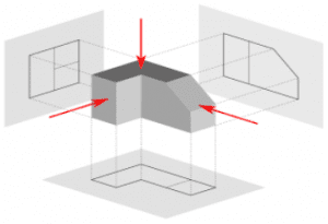
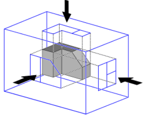
Q10. What is Sections of solids and Section Plane.
Ans – SECTIONING A SOLID –  An object ( here a solid ) is cut by some imaginary cutting plane to understand internal details of that object. The action of cutting is called SECTIONING a solid & The plane of cutting is called SECTION PLANE.

Orthographic and Sectional Orthographic Projections

Q1. Define Orthographic Projection
Ans- Orthographic projection is a means of representing three-dimensional objects in two dimensions. It is a form of parallel projection, in which all the projection lines are orthogonal to the projection plane, resulting in every plane of the scene appearing in affine transformation on the viewing surface.

Q2. Define Elevation, Plan & End View? 
Ans- 

  • Elevation – It is always formed on the V.P [Vertical Plane]  When viewed from the front. 
  • Plan Or Top View – It is always formed on The H.P [Horizontal Plane]  When viewed from the Top.
  • End View – It is made on the left or right of elevation depending on whether its view is from the left or right on the object.

Q3. What do you mean by First Angle and Third Angle Projection Systems?

First Angle Projection

  • This is one of the most common methods used to obtain engineering drawings, mostly for orthographic projections.
  • Orthographic projection is a means of representing three-dimensional objects in two dimensions.
  • The orthographic view typically consists of the top view, front view, and side view. 
  • First angle projection is one of the methods used for orthographic projection drawings and is approved internationally except the United States. 
  • In this projection method, the object is placed in the first quadrant and is positioned in front of the vertical plane and above the horizontal plane.


Third Angle Projection

  • This is another perspective projection method used to represent three-dimensional objects using a series of two-dimensional views. 
  • In third angle projection, the 3D object to be projected is placed in the third quadrant and is positioned behind the vertical plane and below the horizontal plane. 
  • Unlike in first angle projection where the plane of projection is supposedly opaque, the planes are transparent in third angle projection. 
  • This projection method is mainly used in the United States and Japan stipulates the use of third angle projection schema for industrial designs for product fabrication.


Q4. Why are the Projections of Objects not drawn in the Second and Fourth Angle of Projections? 
Ans-The front view and the top view will overlap each other and thus there will be no clarity and it will all be only confusion.

Isometric Projection

Q1. Define  isometric projection

  • Isometric projection is a method for visually representing three-dimensional objects in two dimensions in technical and engineering drawings. It is an axonometric projection in which the three coordinate axes appear equally foreshortened and the angle between any two of them is 120 degrees.

Q2. Differentiates B/W Isometrics Projection And Isometrics View?
 Ans- The View Drawn with the True Scale is Called Isometric Drawing Or Isometric View While That Drawn With The Use Of Isometric Scale Is Called Isometric Projection.

Q3. Name the Method Preferred For Drawing Ellipse In Isometric Projection. 
Ans – Four Centre Method 

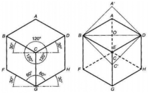
Isometric axes: The Three Lines CB, CD, CG meeting at a point C and making an angle of 1200 with each other are called Isometric axes.
Isometric Lines: The Lines parallel to the Isometric Axis are termed Isometric lines. Example from above fig. AB, AD, GF, GH, BF, DH are Isometric Lines. 
Non-Isometric Lines: The lines which are not parallel to the isometric axes are known as NonIsometric Lines Example from above fig. BD, AC, CF, BG are Non-Isometric Lines. 
Isometric Planes: The planes representing the faces of the cube as well as other planes parallel to these planes are termed as Isometric Planes Example from above fig. ABCD, BCGF, CGHD are Isometric Planes
 Isometric Scale: It is the scale that is used to convert the true length into Isometric Length

Prepare For Your Placements: https://lastmomenttuitions.com/courses/placement-preparation/

/ Youtube Channel: https://www.youtube.com/channel/UCGFNZxMqKLsqWERX_N2f08Q

Follow For Latest Updates, Study Tips & More Content!

/lastmomenttuition

/ Last Moment Tuitions

/ lastmomentdost