Get Latest Exam Updates, Free Study materials and Tips


1. If there are M branch currents, then we can write ___________ number of independent equations.
a) M-2
b) M-1
c) M
d) M+1
Answer: c
Explanation: If there are M branch currents, then we can write M number of independent equations. Number of independent equations = M.
2. If there are M meshes, B branches and N nodes including reference node, the number of mesh currents is given as M=?
a) B + (N+1)
b) B + (N-1)
c) B-(N+1)
d) B-(N-1)
Answer: d
Explanation: If there are M meshes, B branches and N nodes including reference node, the number of mesh currents is given as M= B-(N-1).
3. Determine the current I1 in the circuit shown below using mesh analysis.
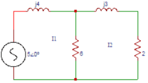
a) 0.955∠-69.5⁰
b) 0.855∠-69.5⁰
c) 0.755∠-69.5⁰
d) 0.655∠-69.5⁰
Answer: b
Explanation: The equation for loop 1 is I1(j4) + 6(I1-I2) = 5∠0⁰. The equation for loop 2 is 6(I1-I2) + (j3) I2 + (2) I2 = 0. Solving the above equations, I1 = 0.855∠-69.5⁰.
4. In the circuit shown in question 3 find the current I2.
a) 0.5∠-90⁰
b) 0.6∠-90⁰
c) 0.7∠-90⁰
d) 0.8∠-90⁰
Answer: b
Explanation: The equation for loop 1 is I1(j4) + 6(I1-I2) = 5∠0⁰. The equation for loop 2 is 6(I1-I2) + (j3) I2 + (2) I2 = 0. Solving the above equations, I2 = 0.6∠-90⁰.
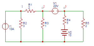
5. Find Z11, Z12, Z13 obtained from the mesh equations in the circuit shown below.
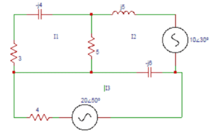
a) (8+j4) Ω, 5 Ω, 0Ω
b) (8-j4) Ω, 5 Ω, 0Ω
c) (8+j4) Ω, – 5 Ω, 0Ω
d) (8-j4) Ω, -5 Ω, 0Ω
Answer: d
Explanation: Z11= self impedance of loop 1 = (5 + 3 – j4) Ω. Z12 = Impedance common to both loop 1 and loop2 = -5Ω. Z13 = No common impedance between loop1 and loop 3 = 0Ω.
6. Determine Z21, Z22, Z23 in the circuit shown in question 5.
a) 5Ω, (5-j1) Ω, j6 Ω
b) -5Ω, (5-j1) Ω, j6 Ω
c) -5Ω, (5+j1) Ω, j6 Ω
d) -5Ω, (5-j1) Ω, – j6 Ω
Answer: b
Explanation: Z21 = common impedance to loop 1 and loop 2 = -5 Ω. Z22 = self impedance of loop2 = (5+j5-j6) Ω. Z23 = common impedance between loop2 and loop 3 = – (-j6) Ω.
7. Find Z31, Z32, Z33 in the circuit shown in question 5.
a) 0Ω, j6Ω, (4-j6) Ω
b) 0Ω, -j6Ω, (4+j6) Ω
c) 0Ω, -j6Ω, (4-j6) Ω
d) 0Ω, j6Ω, (4+j6) Ω
Answer: a
Explanation: Z31 = common impedance to loop 3 and loop 1 = 0 Ω. Z32 = common impedance between loop3 and loop 2 = – (-j6) Ω. Z33 = self impedance of loop 3 = (4-j6) Ω.
8. Find the values of Z11, Z22, Z33 in the circuit shown below.
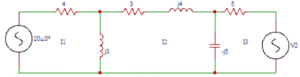
a) (4+j3) Ω, (3-j2) Ω, (5-j5) Ω
b) (4+j3) Ω, (3+j2) Ω, (5-j5) Ω
c) (4-j3) Ω, (3-j2) Ω, (5-j5) Ω
d) (4+j3) Ω, (3-j2) Ω, (5+j5 ) Ω
Answer: b
Explanation: Z11= self impedance of loop 1 = (4 + j3) Ω. Z22 = self impedance of loop2 = (j3+3+j4-j5) Ω. Z33 = self impedance of loop 3 = (-j5+5) Ω.
9. Find the common impedances Z12, Z13, Z21, Z23, Z31, Z32 respectively in the circuit shown in question 8.
a) -j3Ω, 0Ω, -j3Ω, j5Ω, 0Ω, j5Ω
b) j3Ω, 0Ω, -j3Ω, j5Ω, 0Ω, j5Ω
c) j3Ω, 0Ω, -j3Ω, j5Ω, 0Ω,- j5Ω
d) j3Ω, 0Ω, -j3Ω, -j5Ω, 0Ω, j5Ω
Answer: a
Explanation: The common impedances Z12 and Z21 are Z12= Z21 = -j3Ω. The common impedances Z13 and Z31 are Z13 = Z31 =0Ω. The common impedances Z23 and Z32 are Z23 = Z32 = j5Ω.
10. Find the value V2 in the circuit shown in question 9 if the current through (3+j4) Ω is zero.
a) 16∠-262⁰
b) 17∠-262⁰
c) 18∠-262⁰
d) 19∠-262⁰
Answer: b
Explanation: The three loop equations are (4+j3)I1 –(j3)I2 = 20∠0⁰. (-j3)I1 + (3+j2)I2 + (j5)I3 = 0. (j5)I2 + (5-j5)I3 = -V2. The current through (3+j4) Ω is zero, I2= ∆2/∆ =0
        4+j3     20∠0⁰   0
∆2 =  |  -j3       0     j5   |
         0       -V2    5-j5
On solving, V2 = 17∠-262⁰. 11. If there are N nodes in a circuit, then the number of nodal equations that can be formed are? a) N+1 b) N c) N-1 d) N-2 Answer: c Explanation: If there are N nodes in a circuit, then the number of nodal equations that can be formed are N-1. Number of nodal equations = N-1. 12. In the network shown below, find the voltage at node ‘a’.a) 5.22∠104.5⁰ b) 5.22∠-104.5⁰ c) 6.22∠104.5⁰ d) 6.22∠-104.5⁰ Answer: b Explanation: Applying nodal analysis at node ‘a’, (Va-10∠0o)/j6+Va/(-j6)+(Va-Vb)/3=0. Applying nodal analysis at node ‘b’, (Vb-Va)/3+Vb/j4+Vb/j1=0. Solving the above equations we get, Va = 5.22∠-104.5⁰V. 3. Determine the voltage at node ‘b’ in the circuit shown in the question 2. a) -1.34∠-180⁰ b) 1.34∠-180⁰ c) -0.34∠-180⁰ d) 0.34∠-180⁰ Answer: a Explanation: Applying nodal analysis at node ‘a’, (Va-10∠0o)/j6+Va/(-j6)+(Va-Vb)/3=0. Applying nodal analysis at node ‘b’, (Vb-Va)/3+Vb/j4+Vb/j1=0. Solving the above equations we get, Vb = -1.34∠-180⁰V. 14. In the circuit shown below we get a nodal equation as (1/3+1/j4-1/j6)Va—(-1/j6)Vb=x. Find the value of ‘x‘‘.
a) (5∠0o)/3 b) – (5∠0o)/3 c) (10∠0o)/3 d) – (10∠0o)/3 Answer: c Explanation: The general equations are YaaVa+YabVb = I1, YbaVa+YbbVb = I2. We get Yaa=1/3+1/j4+1/(-j6) and the self admittance at node a is the sum of admittances connected to node a. Yab=-(1/(-j6)). I1= (10∠0o)/3=x. 15. Find the value of ‘y’ in the equation –(-1/j6)Va+(1/5+1/j5-1/j6)Vb=y obtained from the circuit shown in the question 4. a) (10∠30o)/5 b) -(10∠30o)/5 c) (5∠30o)/5 d) (-5∠30o)/5 Answer: b Explanation: We got Ybb=1/5+1/j5-1/j6 and Yab=–(-1/j6). The mutual admittance between node b and a is the sum of the admittances between nodes b and a. I2=-(10∠30o)/5=y. 16. In the circuit shown below find the power dissipated by 2Ω resistor.
a) 16.24 b) 17.24 c) 18.24 d) 19.24 Answer: c Explanation: Applying nodal analysis at node ‘a’, (Va-20∠〖30o)/3+Va/(-j4)+Va/(2+j5)=0. On solving, Va = 16.27∠18.91⁰. Current in 2Ω resistor I2= Va/(2+j5)=(16.27∠18.91o)/(5.38∠68.19o )=3.02∠-49.28o. Power dissipated in 2Ω resistor P=I22 R=3.022×2= 18.24W. 17. In the circuit shown in the question 6 determine the power dissipated in 3Ω resistor. a) 7.77 b) 8.77 c) 9.77 d) 10.77 Answer: b Explanation: Current in 3Ω resistor I3 = (-20∠30o+16.27∠18.91o)/3=1.71∠-112o. Power dissipated in 3Ω resistor P=I32 R=1.712×3=8.77W. 18. In the circuit shown in the question 6 find the power output of the source. a) 27 b) 28 c) 29 d) 30 Answer: a Explanation: Total power delivered by the source is the product of voltage and current and is given by power output of the source VIcosφ = 20 x 1.71cos142⁰ = 26.95W. 19. For the circuit shown below, find the voltage across the resistance RL if RL is infinite.
a) 3 b) 2 c) 1 d) 0 Answer: d Explanation: If RL is infinite, the voltage across it will be 0. So the voltage across the resistance RL if RL is infinite is zero. 20. Find the voltage Vab in the circuit shown question 9. a) 21.66∠-45.02⁰ b) 20.66∠-45.02⁰ c) 21.66∠45.02⁰ d) 20.66∠45.02⁰ Answer: c Explanation: Applying nodal analysis at node ‘a’, (Va-20∠0o)/(3+2)+(Va-20∠90o)/(j4+3)=0. On solving, we get Va = 21.66∠45.02⁰V. 21.Consider the circuit shown below. Find the current I1 (A).
a) 1 b) 1.33 c) 1.66 d) 2 Answer: b Explanation: Applying Super mesh analysis, the equations will be I2-I1=2 -10+2I1+I2+4=0. On solving the above equations, I1=1.33A. 22. Find the current I2 (A) in the circuit shown in the question 1. a) 1.33 b) 2.33 c) 3.33 d) 4.33 Answer: c Explanation: Applying Super mesh analysis, the equations will be I2-I1=2 -10+2I1+I2+4=0. On solving the above equations, I2=3.33A. 23. Consider the circuit shown in the figure. Find the current I1 (A).
a) -1 b) -2 c) -3 d) -4 Answer: c Explanation: Applying Super mesh analysis, the equations will be I1+I1+10+I2+I2=0. I1+I2=-5. I2-I1=1. On solving, I1=-3A. 24. Find the current I2 (A) in the figure shown in the question 3. a) -2 b) -1 c) 2 d) 1 Answer: a Explanation: Applying Super mesh analysis, the equations will be I1+I1+10+I2+I2=0. I1+I2=-5. I2-I1=1. On solving, I2=-2A. 25. Find the power (W) supplied by the voltage source in the figure shown in the question 3. a) 0 b) 1 c) 2 d) 3 Answer: a Explanation: I3-I2=2. As I2=-2A, I3=0A. Th term power is the product of voltage and current. So, power supplied by source= 10×0=0W. 26. Find the current i1 in the circuit shown below.
a) 8 b) 9 c) 10 d) 11 Answer: c Explanation: The current in the first loop is equal to 10A. So the current i1 in the circuit is i1 = 10A. 27. Find the current i2 in the circuit shown in the question 6. a) 6.27 b) 7.27 c) 8.27 d) 9.27 Answer: b Explanation: For 2nd loop, 10 + 2(i2-i3) + 3(i2-i1) =0. For 3rd loop, i3 + 2(i3-i2)=10. As i1=10A, On solving above equations, we get i2=7.27A. 28. Find the current i3 in the circuit shown in the question 6. a) 8.18 b) 9.18 c) 10.18 d) 8.8 Answer: a Explanation: For 2nd loop, 10 +2(i2-i3) +3(i2-i1) =0. For 3rd loop, i3 +2(i3-i2)=10. As i1=10A, On solving above equations, we get i3=8.18A. 29. Find the current I1 in the circuit shown below.
a) 8 b) -8 c) 9 d) -9 Answer: b Explanation: Applying Super Mesh analysis, (10+5)I1 – 10(I2) – 5(I3) =50. 2(I2) + I3 + 5(I3-I1) + 10(I2-I1) =0. I2 – I3 = 2. On solving above equations, we get I1=-8A. 30. Find the current I2 in the circuit shown in the question 9. a) 5.3 b) -5.3 c) 7.3 d) -7.3 Answer: d Explanation: Applying Super Mesh analysis, (10+5)I1-10(I2)-5(I3) =50. 2(I2) + I3 + 5(I3-I1) + 10(I2-I1) =0. I2 – I3 =2. On solving above equations, we get I2=-7.3A.
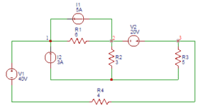
31.Consider the figure shown below. Find the voltage (V) at node 1.
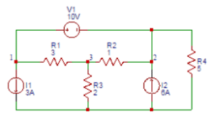
a) 13
b) 14
c) 15
d) 16
Answer: b
Explanation: Applying Super Node Analysis, the combined equation of node 1 and node 2 is (V1-V3)/3+3+(V2-V3)/1-6+V2/5=0. At node 3, (V3-V1)/3+(V3-V2)/1+V3/2=0. Also V1-V2=10. On solving above equations, we get V1= 13.72V ≈ 14V.
32. In the figure shown in the question 1 find the voltage (V) at node 2.
a) 3
b) 4
c) 5
d) 6
Answer: b
Explanation: Applying Super Node Analysis, the combined equation of node 1 and node 2 is (V1-V3)/3+3+(V2-V3)/1-6+V2/5=0. At node 3, (V3-V1)/3+(V3-V2)/1+V3/2=0. Also V1-V2=10. On solving above equations, we get V2 = 3.72V ≈ 4V.
33. In the figure shown in the question 1 find the voltage (V) at node 3.
a) 4.5
b) 5.5
c) 6.5
d) 7.5
Answer: a
Explanation: Applying Super Node Analysis, the combined equation of node 1 and node 2 is (V1-V3)/3+3+(V2-V3)/1-6+V2/5=0. At node 3, (V3-V1)/3+(V3-V2)/1+V3/2=0. Also V1-V2=10. On solving above equations, we get V3 = 4.5V.
34. In the figure shown in the question 1 find the power (W) delivered by the source 6A.
a) 20.3
b) 21.3
c) 22.3
d) 24.3
Answer: c
Explanation: The term power is defined as the product of voltage and current and the power delivered by the source (6A) = V2x6 = 3.72×6 =22.32W.
35. Find the voltage (V) at node 1 in the circuit
a) 18
b) 19
c) 20
d) 21
Answer: b
Explanation: The equation at node 1 is 10= V1/3+(V1-V2)/2. According to super Node analysis, (V1-V2)/2=V2/1+(V3-10)/5+V3/2V2-V3=20. On solving, we get, V1=19V.
36. Find the voltage (V) at node 2 of the circuit shown in the question 5.
a) 11.5
b) 12
c) 12.5
d) 13
Answer: a
Explanation: The equation at node 1 is 10= V1/3+(V1-V2)/2
According to super Node analysis, (V1-V2)/2=V2/1+(V3-10)/5+V3/2V2-V3=20. On solving, we get, V2=11.5V.
37. Find the voltage (V) at node 3 in the figure shown below.
a) 18
b) 20
c) 22
d) 24
Answer: a
Explanation: At node 1, (V1-40-V3)/4+(V1-V2)/6-3-5=0. Applying Super Node Analysis at node 2 and 3, (V2-V1)/6+5+V2/3+V3/5+(V3+40-V1)/4=0. Also V3-V2=20. On solving above equations, V3 = 18.11V ≈ 18V.
38. Find the power absorbed by 5Ω resistor in the figure shown in the question 7.
a) 60
b) 65.5
c) 70.6
d) 75
Answer: b
Explanation: The current through 5Ω resistor = V3/5=18.11/5=3.62A. The power absorbed by 5Ω resistor = (3.62)2 )×5=65.52W.
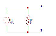
39. Find the value of the voltage (V) in the equivalent voltage source of the current source shown below.
a) 20
b) 25
c) 30
d) 35
Answer: c
Explanation: The value of the voltage (V) in the equivalent voltage source of the current source the voltage across the terminals A and B is (6)( 5) = 30V.
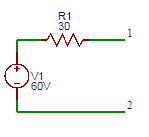
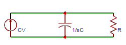
40. Find the value of the current (A) in the equivalent current source of the voltage source shown below.
a) 1
b) 2
c) 3
d) 4
Answer: b
Explanation: The value of the current (A) in the equivalent current source of the voltage source the short circuit current at the terminals A and B is I=60/30=2A.
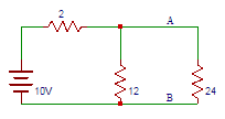
41. Consider the circuit shown below. Find the equivalent Thevenin’s voltage between nodes A and B.
a) 8
b) 8.5
c) 9
d) 9.5
Answer: b
Explanation: The thevenin’s voltage is equal to the open circuit voltage across the terminals AB that is across 12Ω resistor. Vth = 10×12/14 = 8.57V.
42. In the circuit shown above in question 1 find the thevenin’s resistance between terminals A and B.
a) 1
b) 2
c) 1.7
d) 2.7
Answer: c
Explanation: The resistance into the open circuit terminals is equal to the thevenin’s resistance => Rth = (12×2)/14 = 1.71Ω.
43. In the figure shown above in question 1 find the current flowing through 24Ω resistor.
a) 0.33
b) 0.66
c) 0
d) 0.99
Answer: a
Explanation: The equivalent thevenin’s model of the circuit shown is
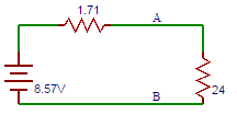
I=8.57/(2.4+1.71)=0.33A.
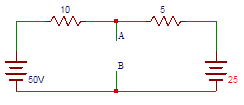
44. Determine the equivalent thevenin’s voltage between terminals A and B in the circuit shown below.
a) 0.333
b) 3.33
c) 33.3
d) 333
Answer: c
Explanation: Let us find the voltage drop across terminals A and B. 50-25=10I+5I => I=1.67A. Voltage drop across 10Ω resistor = 10×1.67=16.7V. So, Vth=VAB=50-V=50-16.7=33.3V.
45. Find the equivalent thevenin’s resistance between terminals A and B in the circuit shown above in question 4.
a) 333
b) 33.3
c) 3.33
d) 0.333
Answer: c
Explanation: To find Rth, two voltage sources are removed and replaced with short circuit. The resistance at terminals AB then is the parallel combination of the 10Ω resistor and 5Ω resistor => Rth=(10×5)/15=3.33Ω.
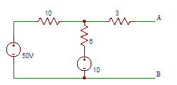
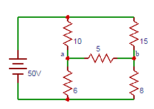
46. Determine the equivalent thevenin’s voltage between terminals A and B in the circuit shown below.
a) 5
b) 15
c) 25
d) 35
Answer: c
Explanation: Current through 3Ω resistor is 0A. The current through 6Ω resistor = (50-10)/(10+6)=2.5A. The voltage drop across 6Ω resistor = 25×6=15V. So the voltage across terminals A and B = 0+15+10 = 25V.
47. Find the equivalent thevenin’s resistance between terminals A and B in the circuit shown above in question 6.
a) 6
b) 6.25
c) 6.5
d) 6.75
Answer: d
Explanation: To find Rth, two voltage sources are removed and replaced with short circuit => Rth=(10×6)/(10+6)+3=6.75Ω.
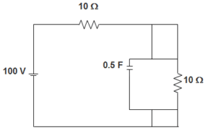
48. Determine the equivalent thevenin’s voltage between terminals ‘a’ and ‘b’ in the circuit shown below.
a) 0.7
b) 1.7
c) 2.7
d) 3.7
Answer: c
Explanation: The voltage at terminal a is Va=(100×6)/16=37.5V, The voltage at terminal b is Vb=(100×8)/23=34.7V. So the voltage across the terminals ab is Vab=Va-Vb=37.5-34.7=2.7V.
49. Find the equivalent thevenin’s resistance between terminals A and B in the circuit shown above in question 8.
a) 6
b) 7
c) 8
d) 9
Answer: d
Explanation: To find Rth, two voltage sources are removed and replaced with short circuit => Rab=(6×10)/(6+10)+(8×15)/(8+15)=8.96≅9V.
50. Find the current through 5Ω resistor in the circuit shown above in question 8.
A) 0.1
b) 0.2
c) 0.3
d) 0.4
Answer: b
Explanation: The Equivalent Thevenin’s circuit for the circuit shown above is
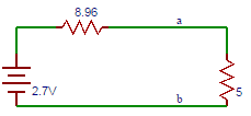
I=2.7/(8.96+5)=0.193A≅0.2A.
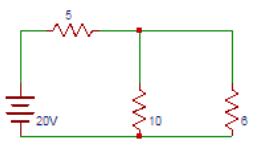
51. Find the current flowing between terminals A and B of the circuit shown below.
a) 1
b) 2
c) 3
d) 4
Answer: d
Explanation: The magnitude of the current in the Norton’s equivalent circuit is equal to the current passing through the short circuited terminals that is I=20/5=4A.
52. Find the equivalent resistance between terminals A and B of the circuit shown below.
a) 0.33
b) 3.33
c) 33.3
d) 333
Answer: b
Explanation: Norton’s resistance is equal to the parallel combination of both the 5Ω and 10Ω resistors that is R = (5×10)/15 = 3.33Ω.
53. Find the current through 6Ω resistor in the circuit shown above.
a) 1
b) 1.43
c) 2
d) 2.43
Answer: b
Explanation: The current passing through the 6Ω resistor and the voltage across it due to Norton’s equivalent circuit is I = 4×3.33/(6+3.33) = 1.43A.
54. Find the voltage drop across 6Ω resistor in the circuit shown above.
a) 6.58
b) 7.58
c) 8.58
d) 9.58
Answer: c
Explanation: The voltage across the 6Ω resistor is V = 1.43×6 = 8.58V. So the current and voltage have same values both in the original circuit and Norton’s equivalent circuit.
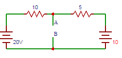
55. Find the current flowing between terminals A and B.
a) 1
b) 2
c) 3
d) 4
Answer: d
Explanation: Short circuiting terminals A and B, 20-10(I1)=0, I1=2A. 10-5(I2), I2=2A. Current flowing through terminals A and B= 2+2 = 4A.
56. Find the equivalent resistance between terminals A and B
a) 3
b) 3.03
c) 3.33
d) 3.63
Answer: c
Explanation: The resistance at terminals AB is the parallel combination of the 10Ω resistor and the 5Ω resistor => R = ((10×5))/(10+5) = 3.33Ω.
57. Find the current flowing between terminals A and B obtained in the equivalent Nortan’s circuit.
a) 8
b) 9
c) 10
d) 11
Answer: d
Explanation: To solve for Norton’s current we have to find the current passing through the terminals A and B. Short circuiting the terminals a and b, I=100/((6×10)/(6+10)+(15×8)/(15+8))=11.16 ≅ 11A.
58. Find the equivalent resistance between terminals A and B obtained in the equivalent Nortan’s circuit.
a) 8
b) 9
c) 10
d) 11
Answer: b
Explanation: The resistance at terminals AB is the parallel combination of the 10Ω resistor and the 6Ω resistor and parallel combination of the 15Ω resistor and the 8Ω resistor => R=(10×6)/(10+6)+(15×8)/(15+8)=8.96≅9Ω.
59. Find the current through 5Ω resistor in the circuit shown above.
a) 7
b) 8
c) 9
d) 10
Answer: a
Explanation: To solve for Norton’s current we have to find the current passing through the terminals A and B. Short circuiting the terminals a and b I=11.16×8.96/(5+8.96) = 7.16A.
60. Find the voltage drop across 5Ω resistor in the circuit shown above.
a) 33
b) 34
c) 35
d) 36
Answer: d
Explanation: The voltage drop across 5Ω resistor in the circuit is the product of current and resistance => V = 5×7.16 = 35.8 ≅ 36V.
61. The maximum power is delivered from a source to its load when the load resistance is ______ the source resistance.
a) greater than
b) less than
c) equal to
d) less than or equal to
Answer: c
Explanation: The maximum power is delivered from a source to its load when the load resistance is equal to the source resistance. The maximum power transfer theorem can be applied to both dc and ac circuits.
62. If source impedance is complex, then maximum power transfer occurs when the load impedance is _______ the source impedance.
a) equal to
b) negative of
c) complex conjugate of
d) negative of complex conjugate of
Answer: c
Explanation: The maximum power transfer theorem can be applied to complex impedance circuits. If source impedance is complex, the maximum power transfer occurs when the load impedance is complex conjugate of the source impedance.
63. If the source impedance is complex, then the condition for maximum power transfer is?
a) ZL = ZS
b) ZL = ZS*
c) ZL = -ZS
d) ZL = -ZS*
Answer: b
Explanation: The maximum power is transferred when the load resistance is equal to the source resistance. The condition for maximum power transfer is ZL = ZS*.
64. If ZL = ZS*, then?
a) RL = 1
b) RL = 0
c) RL = -RS
d) RL = RS
Answer: d
Explanation: If ZL = ZS*, then RL = RS. This means that the maximum power transfer occurs when the load impedance is equal to the complex conjugate of source impedance ZS.
65. For ZL = ZS*, the relation between XL and XS is?
a) XL = XS
b) XL = 0
c) XL = 1
d) XL = -XS
Answer: d
Explanation: For ZL = ZS*, the relation between XL and XS is XL = -XS. Maximum power transfer is not always desirable since the transfer occurs at a 50 percent efficiency.
66. In the circuit shown below, find the value of load impedance for which source delivers maximum power.
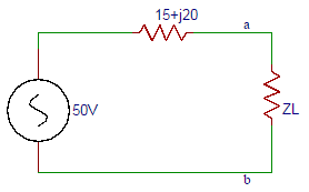
a) 15-j20
b) 15+j20
c) 20-j15
d) 20+j15
Answer: a
Explanation: The maximum power transfer occurs when the load impedance is equal to the complex conjugate of source impedance ZS. ZL = ZS* = (15-j20) Ω.
67. The load current in the circuit shown in the question 6 is?
a) 1.66∠90⁰
b) 1.66∠0⁰
c) 2.66∠0⁰
d) 2.66∠90⁰
Answer: b
Explanation: The load current is the ratio of voltage to the impedance. So the load current is I=(50∠0o)/(15+j20+15-j20) =1.66∠0o A.
68. The maximum power delivered by the source in the circuit shown in the question 6 is?
a) 39.33
b) 40.33
c) 41.33
d) 42.33
Answer: c
Explanation: The term power is defined as the product of the square of current and the impedance. So the maximum power delivered by the source in the circuit is P = I2RxZ = 1.662×15 = 41.33W.
69. For the circuit shown, the resistance R is variable from 2Ω to 50Ω. What value of RS results in maximum power transfer across terminals ‘ab’.
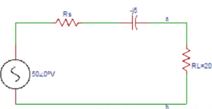
a) 1
b) 2
c) 3
d) 4
Answer: b
Explanation: As RL is fixed, the maximum power transfer theorem does not apply. Maximum current flows in the circuit when RS is minimum. So RS = 2Ω.
70. Find the maximum power delivered by the source in the circuit shown in the question 9.
a) 96.6
b) 97.6
c) 98.6
d) 99.6
Answer: c
Explanation: ZT = RS – j5+ RL = 2-j5+20 = 22.56∠-12.8⁰Ω. I=VS/ZT = -50∠0⁰/22.56∠-12.8⁰ = 2.22∠-12.8⁰A. P = I2R= 2.222×20=98.6W.
1) According to the graph theory of loop analysis, how many equilibrium equations are required at a minimum level in terms of number of branches (b) and number of nodes (n) in the graph?
a. n-1
b. b+(n-1)
c. b-(n-1)
d. b/ n-1
ANSWER: b-(n-1)
Explanation:
No explanation is available for this question!
2) What would be an order of branch impedance matrix for the below stated KVL equilibrium equation on the basis of loop or mesh analysis?
E = B (Vs – Zb Is)
a. b x 1
b. b x b
c. b-n+1) x 1
d. (b-n+1) x b
ANSWER: b x b
Explanation:
No explanation is available for this question!
3) Consider the assertions given below. Which among them do/does not specify/ies the property of ‘Complete Incidence Matrix’?
a. Determinant of a loop of a complete incidence matrix is always zero
b. Addition of all entries in any column should never be equal to zero
c. Rank of connected or oriented graph is always ‘n-1’
d. All of the above
ANSWER: Addition of all entries in any column should never be equal to zero
Explanation:
No explanation is available for this question!
4) Which parameter should be essentially equal to the number of nodes in the network in accordance to the principle of duality?
a. Total impedance
b. Total admittance
c. Number of meshes
d. Number of voltage sources
ANSWER: Number of meshes
Explanation:
No explanation is available for this question!
5) How many fundamental cutsets will be generated for a graph with ‘n’ number of nodes?
a. n+1
b. n-1
c. n2(n-1)
d. n/ n-1
ANSWER: n-1
Explanation:
No explanation is available for this question!
6) What will be the number of trees, if the graph exhibits reduction in the form of reduced incident matrix given below?
a. 16
b. 24
c. 26
d. 28
ANSWER: 24
Explanation:
No explanation is available for this question!
7) According to the linear graph theory, the number of possible trees is always equal to the determinant of product of ______
a. Only complete incidence matrix
b. Reduced incidence matrix & its transpose
c. Cut-Set matrix
d. Tie-set matrix
ANSWER: Reduced incidence matrix & its transpose
Explanation:
No explanation is available for this question!
8) What will be the value of a rectangular (complete incidence) matrix, if an associated branch is oriented towards the node?
a. 1
b. -1
c. 0
d. Not defined (∞)
ANSWER: -1
Explanation:
No explanation is available for this question!
9) How many number of minimum end nodes or terminal nodes are involved in a tree, according to its properties?
a. Only one
b. Two
c. Four
d. Infinite
ANSWER: Two
Explanation:
No explanation is available for this question!
10) Which among the below specified assertions are precisely related to the conditions applicable for a path to be an improper subgraph?
A. Incidence of a single branch at a terminating node
B. Incidence of two branches at the remaining nodes
a. A is true & B is false
b. A is false & B is true
c. Both A & B are true
d. Both A & B are false
ANSWER: Both A & B are true
11. The direction of the cut-set is?
a) same as the direction of the branch current
b) opposite to the direction of the link current
c) same as the direction of the link current
d) opposite to the direction of the branch current
Answer: a
Explanation: A cut-set is a minimal set of branches of a connected graph such that the removal of these branches causes the graph to be cut into exactly two parts. The direction of the cut-set is same as the direction of the branch current.
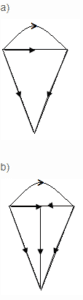
12. Consider the graph shown below. The direction of the cut-set of node ‘a’ is?

a) right
b) left
c) upwards
d) downwards
Answer: c
Explanation: The direction of the cut set at node ‘a’ will be the direction of the branch current at node ‘a’. So the direction of the current will be upwards.
13. Consider the graph shown above in question 2. The direction of the cut-set at node ‘b’ will be?
a) upwards
b) right
c) downwards
d) left
Answer: b
Explanation: The direction of the current will be towards right. The direction of the cut set at node ‘b’ will be the direction of the branch current at node ‘b’. So the direction of the current will be towards right.
14. In the graph shown above in the question 2, the direction of the cut-set at node ‘c’ is?
a) downwards
b) upwards
c) left
d) right
Answer: b
Explanation: The direction of the cut set at node ‘c’ will be the direction of the branch current at node ‘c’. So the direction of the current will be upwards.
15. In the graph shown in the question 2, the direction of the cut-set at node ‘d’ will be?
a) left
b) downwards
c) right
d) upwards
Answer: c
Explanation: The direction of the cut set at node ‘d’ will be the direction of the branch current at node ‘d’. So the direction of the current will be upwards.
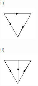
16. The row formed at node ‘a’ in the cut set matrix in the figure shown in question 2 is?
I1 I2 I3 I4 I5 I6 I7 I8
a) +1 +1 +1 +1 0 0 0 0
b) +1 0 0 0 +1 0 0 +1
c) -1 0 0 0 -1 0 0 -1
d) -1 -1 0 0 -1 -1 0 0
Answer: b
Explanation: The direction of the cut set at node ‘a’ is towards node ‘a’. So the current direction of I1 is same as cut set direction. So it is +1. Similarly for all other currents.
17. The row formed at node ‘c’ in the cut set matrix in the figure shown question 2 is?
a) -1 -1 0 0 +1 -1 0 0
b) 0 0 +1 0 0 -1 -1 0
c) +1 0 0 0 +1 0 0 +1
d) -1 0 0 0 -1 0 0 -1
Answer: b
Explanation: The direction of the cut set at node ‘c’ is away from node ‘c’. So the current direction of I3 is same as cut set direction. So it is +1. Similarly for all other currents.
18. The number of cut set matrices formed from a graph is?
a) NN-1
b) NN
c) NN-2
d) NN+1
Answer: c
Explanation: For every tree, there will be a unique cut set matrix. So there will be NN-2 cut set matrices.
19. For every tree there will be _____ number of cut set matrices.
a) 1
b) 2
c) 3
d) 4
Answer: a
Explanation: For every tree, there will a unique cut set matrix. So, number of cut-set matrices for every tree = 1.
20. If a row of the cut set matrix formed by the branch currents of the graph is shown below. Then which of the following is true?
I1 I2 I3 I4 I5 I6 I7 I8
-1 -1 0 0 +1 -1 0 0
a) -V1-V2+V5-V6=0
b) -I1-I2+I5-I6=0
c) -V1+V2+V5-V6=0
d) -I1+I2+I5-I6=0
Answer: b
Explanation: KCL equations are derived from cut set matrix and these include currents not voltages. So, -I1-I2+I5-I6=0.
21. A graph is said to be a directed graph if ________ of the graph has direction.
a) 1 branch
b) 2 branches
c) 3 branches
d) every branch
Answer: d
Explanation: If every branch of the graph has direction, then the graph is said to be a directed graph. If the graph does not have any direction then that graph is called undirected graph.
22. The number of branches incident at the node of a graph is called?
a) degree of the node
b) order of the node
c) status of the node
d) number of the node
Answer: a
Explanation: Nodes can be incident to one or more elements. The number of branches incident at the node of a graph is called degree of the node.
23. If no two branches of the graph cross each other, then the graph is called?
a) directed graph
b) undirected graph
c) planar graph
d) non-planar graph
Answer: c
Explanation: If a graph can be drawn on a plane surface such that no two branches of the graph cross each other, then the graph is called planar graph .
24. Consider the graph given below. Which of the following is a not a tree to the graph?
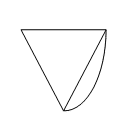
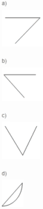
Answer: d
Explanation: Tree is sub graph which consists of all node of original graph but no closed paths. So, ‘d’ is not a tree to the graph.
25. Number of twigs in a tree are? n- number of nodes
a) n
b) n+1
c) n-1
d) n-2
Answer: c
Explanation: Twig is a branch in a tree. Number of twigs in a tree are n-1. If there are 4 nodes in a tree then number of possible twigs are 3.
26. Loops which contain only one link are independent are called?
a) open loops
b) closed loops
c) basic loops
d) none of the above
Answer: c
Explanation: The addition of subsequent link forms one or more addition al loops. Loops which contain only one link are independent are called basic loops.
27. If the incident matrix of a graph is given below. The corresponding graph is?
     a    b   c  d   e    f
     1   +1   0  +1   0   0   +1
     2   -1  -1   0  +1   0    0
     3    0  +1   0   0   +1  -1
     4    0   0  -1  -1   -1   0
Answer: b
Explanation: For the given incidence matrix,
     a    b   c  d   e    f
     1   +1   0  +1   0   0   +1
     2   -1  -1   0  +1   0    0
     3    0  +1   0   0   +1  -1
     4    0   0  -1  -1   -1   0
the corresponding graph is ‘b’ considering the directions specified in the graph.
28. If A represents incidence matrix, I represents branch current vectors, then?
a) AI = 1
b) AI = 0
c) AI = 2
d) AI= 3
Answer: b
Explanation: If A represents incidence matrix, I represents branch current vectors, then the relation is AI= 0 that is its characteristic equation must be equated to zero
29. If a graph consists of 5 nodes, then the number of twigs in the tree are?
a) 1
b) 2
c) 3
d) 4
Answer: d
Explanation: Number of twigs= n-1. As given number of nodes are 5 then n = 5. On substituting in the equation, number of twigs =5 -1 = 4.
30. If there are 4 branches, 3 nodes then number of links in a co-tree are?
a) 2
b) 4
c) 6
d) 8
Answer: a
Explanation: Number of links = b-n+1. Given number of branches = 4 and number of nodes = 3. On substituting in the equation, number of links in a co-tree = 4 – 3 + 1 = 2.
31. The current in a closed path in a loop is called?
a) loop current
b) branch current
c) link current
d) twig current
Answer: c
Explanation: In a loop there exists a closed path and a circulating current which is called link current. The current in any branch can be found by using link currents.
32. Tie-set is also called?
a) f loop
b) g loop
c) d loop
d) e loop
Answer: a
Explanation: The fundamental loop formed by one link has a unique path in the tree joining the two nodes of the link. This loop is also called f-loop.
33. Consider the graph shown below. If a tree of the graph has branches 4, 5, 6, then one of the twigs will be?
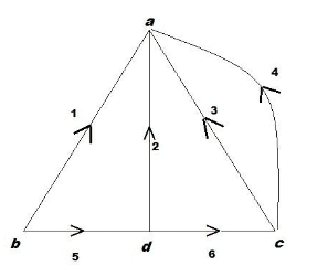
a) 1
b) 2
c) 3
d) 4
Answer: d
Explanation: Branches of the tree are called twigs. So 4, 5, 6 are the twigs of the tree. The current in any branch of a graph can be found by using link currents.
34. Consider the graph shown in the question 3 above. If a tree of the graph has branches 4, 5, 6, then one of the links will be?
a) 3
b) 4
c) 5
d) 6
Answer: a
Explanation: The branches of the co-tree are called links. So the links will be 1, 2, 3. For a given tree of a graph addition of each link between any two nodes form a loop called fundamental loop.
35. The loop current direction of the basic loop formed from the tree of the graph is?
a) same as the direction of the branch current
b) opposite to the direction of the link current
c) same as the direction of the link current
d) opposite to the direction of the branch current
Answer: c
Explanation: The loop current direction of the basic loop formed from the tree of the graph is same as the direction of the link current.
36. Consider the graph shown below. The direction of the loop currents will be? (ACW – Anticlockwise, CW – Clockwise).
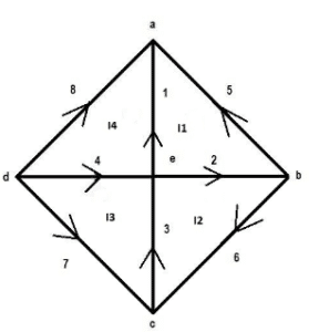
a) I1 ACW
b) I2 ACW
c) I3 CW
d) I4 ACW
Answer: a
Explanation: The direction of the loop current will be along the direction of the link current in a basic loop. So I1 – ACW, I2 – CW, I3 – ACW, I4 – CW.
37. For Tie-set matrix, if the direction of current is same as loop current, then we place ___ in the matrix.
a) +1
b) -1
c) 0
d) +1 or -1
Answer: a
Explanation: For Tie-set matrix, if the direction of current is same as loop current, then we place +1 in the matrix.
38. If a row of the tie set matrix is as given below, then its corresponding equation will be?
1 2 3 4 5 6 7 8
I1 -1 +1 0 0 +1 0 0 0
a) -V1+V2+V3=0
b) -I1+I2+I3=0
c) -V1+V2-V3=0
d) -I1+I2-I3=0
Answer: a
Explanation: KVL equations are derived from tie set matrix and these include voltages not currents. So, -V1+V2+V3=0.
39. The matrix formed by link branches of a tie set matrix is?
a) Row matrix
b) Column matrix
c) Diagonal matrix
d) Identity matrix
Answer: d
Explanation: As the direction of the basic loops of the tree are taken along the direction of the link currents, then the matrix formed by the link currents will be a identity matrix.
40. The number of tie set matrices formed from a graph are?
a) NN-1
b) NN
c) NN-2
d) NN+1
Answer: c
Explanation: For every tree, there will be a unique tie set matrix. So there will be NN-2 tie set matrices.
1. The expression of current in R- L circuit is?
a) i=(V/R)(1+exp((R/L)t))
b) i=-(V/R)(1-exp((R/L)t))
c) i=-(V/R)(1+exp((R/L)t))
d) i=(V/R)(1-exp((R/L)t))
Answer: d
Explanation: The expression of current in R- L circuit is i = (V/R)-(V/R)exp((R/L)t). On solving we get i = (V/R)(1-exp((R/L)t) ).
2. The steady state part in the expression of current in the R-L circuit is?
a) (V/R)(exp((R/L)t))
b) (V/R)(-exp((R/L)t))
c) V/R
d) R/V
Answer: c
Explanation: The steady state part in the expression of current in the R-L circuit is steady state part = V/R. When the switch S is closed, the response reaches a steady state value after a time interval.
3. In the expression of current in the R-L circuit the transient part is?
a) R/V
b) (V/R)(-exp((R/L)t))
c) (V/R)(exp((R/L)t))
d) V/R
Answer: b
Explanation: The expression of current in the R-L circuit has the transient part as
(V/R)(-exp((R/L)t) ). The transition period is defined as the time taken for the current to reach its final or steady state value from its initial value.
4. The value of the time constant in the R-L circuit is?
a) L/R
b) R/L
c) R
d) L
Answer: a
Explanation: The time constant of a function (V/R)e-(R/L)t is the time at which the exponent of e is unity where e is the base of the natural logarithms. The term L / R is called the time constant and is denoted by ‘τ’.
5. After how many time constants, the transient part reaches more than 99 percent of its final value?
a) 2
b) 3
c) 4
d) 5
Answer: d
Explanation: After five time constants, the transient part of the response reaches more than 99 percent of its final value.
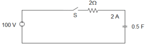
6. A series R-L circuit with R = 30Ω and L = 15H has a constant voltage V = 60V applied at t = 0 as shown in the figure. Determine the current (A) in the circuit at t = 0+.
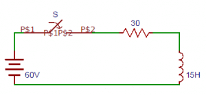
a) 1
b) 2
c) 3
d) 0
Answer: d
Explanation: Since the inductor never allows sudden changes in currents. At t = 0+ that just after the initial state the current in the circuit is zero.
7. The expression of current obtained from the circuit in terms of differentiation from the circuit shown in the question 6?
a) di/dt+i=4
b) di/dt+2i=0
c) di/dt+2i=4
d) di/dt-2i=4
Answer: c
Explanation: Let the i be the current flowing through the circuit. By applying Kirchhoff’s voltage law, we get 15 di/dt+30i=60 => di/dt+2i=4.
8. The expression of current from the circuit shown in the question 6 is?
a) i=2(1-e-2t)A
b) i=2(1+e-2t)A
c) i=2(1+e2t)A
d) i=2(1+e2t)A
Answer: a
Explanation: At t = 0+ the current in the circuit is zero. Therefore at t = 0+, i = 0 => 0 = c + 2 =>c = -2. Substituting the value of ‘c’ in the current equation, we have i = 2(1-e-2t)A.
9. The expression of voltage across resistor in the circuit shown in the question 6 is?
a) VR =60(1+e2t)V
b) VR =60(1-e-2t)V
c) VR =60(1-e2t)V
d) VR =60(1+e-2t)V
Answer: b
Explanation: Voltage across the resistor VR = iR. On substituting the expression of current we get voltage across resistor = (2(1-e-2t) )×30=60(1-e-2t)V.
10. Determine the voltage across the inductor in the circuit shown in the question 6 is?
a) VL =60(-e-2t)V
b) VL =60(e2t)V
c) VL =60(e-2t)V
d) VL =60(-e2t)V
Answer: c
Explanation: Voltage across the inductor VL = Ldi/dt. On substituting the expression of current we get voltage across the inductor = 15×(d/dt)(2(1-e-2t)))=60(e-2t)V.
11. The current in the R-L circuit at a time t = 0+ is?
a) V/R
b) R/V
c) V
d) R
Answer: a
Explanation: The capacitor never allows sudden changes in voltage, it will act as a short circuit at t = 0+. So the current in the circuit at t = 0+ is V/R.
12. The expression of current in R- C circuit is?
a) i=(V/R)exp(t/RC )
b) i=(V/R)exp(-t/RC )
c) i=(V/R)-exp(t/RC )
d) i=(V/R)-exp(-t/RC )
Answer: b
Explanation: The particular solution of the current equation is zero. So the expression of current in R- C circuit is i=(V/R)exp(-t/RC ).
13. In an R-C circuit, when the switch is closed, the response ____________
a) do not vary with time
b) decays with time
c) rises with time
d) first increases and then decreases
Answer: b
Explanation: In a R-C circuit, when the switch is closed, the response decays with time that is the response V/R decreases with increase in time.
14. The time constant of an R-C circuit is?
a) RC
b) R/C
c) R
d) C
Answer: a
Explanation: The time constant of an R-C circuit is RC and it is denoted by τ and the value of τ in dc response of R-C circuit is RC sec.
15. After how many time constants, the transient part reaches more than 99 percent of its final value?
a) 2
b) 3
c) 4
d) 5
Answer: d
Explanation: After five time constants, the transient part of the response reaches more than 99 percent of its final value.
16.A series R-C circuit consists of resistor of 10 and capacitor of 0.1F as shown in the figure. A constant voltage of 20V is applied to the circuit at t = 0. What is the current in the circuit at t = 0?
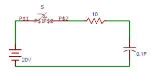
a) 1
b) 2
c) 3
d) 4
Answer: b
Explanation: At t = 0, switch S is closed. Since the capacitor does not allow sudden changes in voltage, the current in the circuit is i = V/R = 20/10 = 2A. At t = 0, i = 2A.
17. The expression of current obtained from the circuit in terms of differentiation from the circuit shown in the question 6?
a) di/dt+i=1
b) di/dt+i=2
c) di/dt+i=3
d) di/dt+i=0
Answer: d
Explanation: By applying Kirchhoff’s law, we get
![]()
Differentiating with respect to t, we get 10 di/dt+i/0.1=0 => di/dt+i=0.
18. The current equation in the circuit shown in the question 6 is?
a) i=2(e-2t)A
b) i=2(e2t)A
c) i=2(-e-2t)A
d) i=2(-e2t)A
Answer: a
Explanation: At t = 0, switch S is closed. Since the capacitor does not allow sudden changes in voltage, the current in the circuit is i = V/R = 20/10 = 2A. At t = 0, i = 2A. The current equation is i=2(e-2t)A.
19. The expression of voltage across resistor in the circuit shown in the question 6 is?
a) VR =20(et)V
b) VR =20(-e-t)V
c) VR =20(-et)V
d) VR =20(e-t)V
Answer: d
Explanation: The expression of voltage across resistor in the circuit is VR = iR =(2(e-t ) )×10=20(e-t )V.
20. Determine the voltage across the capacitor in the circuit shown in the question 6 is?
a) VC =60(1-e-t )V
b) VC =60(1+et )V
c) VC =60(1-et )V
d) VC =60(1+e-t )V
Answer: a
Explanation: The expression of voltage across capacitor in the circuit VC = V(1-e-t/RC) =20(1-e-t)V.
21. For an R-L-C circuit, we get [D – (K1 + K2)][D – (K1 – K2)] i = 0. If K2 is positive, then the curve will be?
a) damped
b) over damped
c) under damped
d) critically damped
Answer: b
Explanation: For an R-L-C circuit, we get [D – (K1 + K2)][D – (K1 – K2)] i = 0. If K2 is positive, then the curve will be over damped response.
22. If the roots of an equation are real and unequal, then the response will be?
a) critically damped
b) under damped
c) over damped
d) damped
Answer: c
Explanation: If the roots of an equation are real and unequal, then the response will be over damped response. Over damped response of a system is defined as the system returns (exponentially decays) to equilibrium without oscillating.
23. If the roots of an equation are complex conjugate, then the response will be?
a) over damped
b) critically damped
c) damped
d) under damped
Answer: d
Explanation: If the roots of an equation are complex conjugate, then the response will be under damped response. Damping is an influence within or upon an oscillatory system that has the effect of reducing, restricting or preventing its oscillations.
24. If the roots of an equation are real and equal, then the response will be?
a) over damped
b) damped
c) critically damped
d) under damped
Answer: c
Explanation: If the roots of an equation are real and equal, then the response will be critically damped response. For a critically damped system, the system returns to equilibrium as quickly as possible without oscillating.
25. The circuit shown in the figure consists of resistance, capacitance and inductance in series with a 100V source when the switch is closed at t = 0. Find the equation obtained from the circuit in terms of current.
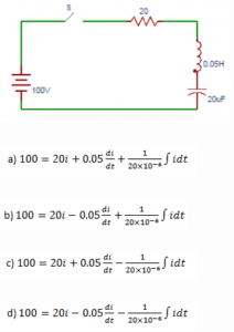
Answer: a
Explanation: At t = 0, switch S is closed when the 100V source is applied to the circuit and results in the following differential equation.
![]()
26. Replacing the differentiation with D1, D2 in the equation obtained from the question 5. Find the values of D1, D2.
a) 200±j979.8
b) -200±j979.8
c) 100±j979.8
d) -100±j979.8
Answer: b
Explanation: Let the roots of the characteristic equation are denoted by D1, D2. So on differentiating the equation obtained in the question 5, we get D1 = -200+j979.8, D2 = -200-j979.8.
27. The expression of current from the circuit shown in the question 5.
a) i=e-200t [c1 cos979.8t+c2 979.8t]A
b) i=e200t [c1 cos979.8t-c2 979.8t]A
c) i=e-200t [c1 cos979.8t-c2 979.8t]A
d) i=e200t [c1 cos979.8t+c2 979.8t]A
Answer: a
Explanation: The expression of current from the circuit will be i = eK1t[c1cosK1t + c2sinK2t]. So, i=e-200t [c1 cos979.8t+c2 979.8t]A.
28. At time t = 0, the value of current in the circuit shown in the question 5.
a) 1
b) 2
c) 3
d) 0
Answer: d
Explanation: At t = 0 that is initially the current flowing through the circuit is zero that is i = 0. So, i = 0.
29. The voltage across the inductor at t = 0 in the circuit shown in the question 5.
a) 50
b) 100
c) 150
d) 200
Answer: b
Explanation: At t = 0, that is initially the voltage across the inductor is 100V. => V = 100V. So we can write Ldi/dt = 100.
30. The current equation obtained from the circuit shown in the question 5.
a) i=e-200t (1.04 sin979.8t)A
b) i=e-200t (2.04 sin979.8t)A
c) i=e-200t (3.04 sin979.8t)A
d) i=e-200t (4.04 sin979.8t)A
Answer: b
Explanation: On solving the values of c1, c2 are obtained as c1 = 0, c2 = 2.04. So, the current equation is i=e-200t (2.04 sin979.8t)A.
31. The resistance element __________ while going from the time domain to frequency domain.
a) does not change
b) increases
c) decreases
d) increases exponentially
Answer: a
Explanation: The s-domain equivalent circuit of a resistor is simply resistance of R ohms that carries a current I ampere seconds and has a terminal voltage V volts-seconds. The resistance element does not change while going from the time domain to the frequency domain.
32. The relation between current and voltage in case of inductor is?
a) v=Ldt/di
b) v=Ldi/dt
c) v=dt/di
d) v=di/dt
Answer: b
Explanation: Consider an inductor with an initial current Io. The time domain relation between current and voltage is v=Ldi/dt.
33. The s-domain equivalent of the inductor reduces to an inductor with impedance?
a) L
b) sL
c) s2L
d) s3L
Answer: b
Explanation: If the initial energy stored in the inductor is zero, the equivalent circuit of the inductor reduces to an inductor with impedance sL ohms.
34. The voltage and current in a capacitor are related as?
a) i=Cdt/dv
b) v=Cdv/dt
c) i=Cdv/dt
d) v=Cdt/dv
Answer: c
Explanation: Consider an initially charged capacitor and the initial voltage on the capacitor is Vo. The voltage current relation in the time domain is i=Cdv/dt.
35. The s-domain equivalent of the capacitor reduces to an capacitor with impedance?
a) sC
b) C
c) 1/C
d) 1/sC
Answer: d
Explanation: The s-domain equivalent of the capacitor can be derived for the charged capacitor and it reduces to an capacitor with impedance 1/sC.
36. From the circuit shown below, find the value of current in the loop.

a) (V/R)/(s+1/RC)
b) (V/C)/(s+1/R)
c) (V/C)/(s+1/RC)
d) (V/R)/(s+1/R)
Answer: a
Explanation: Applying Kirchhoff’s law around the loop, we have V/s=1/sC I+RI. Solving above equation yields I=CV/(RCS+1)=(V/R)/(s+1/RC).
37. After taking the inverse transform of current in the circuit shown in question 6, the value of current is?
a) i=(V/C)e-t/R
b) i=(V/C)e-t/RC
c) i=(V/R)e-t/RC
d) i=(V/R)e-t/R
Answer: c
Explanation: We had assumed the capacitor is initially charged to Vo volts. By taking the inverse transform of the current, we get i=(V/R) e-t/RC.
38. The voltage across the resistor in the circuit shown in question 6 is?
a) Vet/R
b) Ve-t/RC
c) Ve-t/R
d) Vet/RC
Answer: b
Explanation: We can determine the voltage v by simply applying the ohm’s law from the circuit. And applying the Ohm’s law from the circuit v = Ri = Ve-t/RC.
39. The voltage across the resistor in the parallel circuit shown is?
a) V/(s-1/R)
b) V/(s-1/RC)
c) V/(s+1/RC)
d) V/(s+1/C)
Answer: c
Explanation: The given circuit is converted to parallel equivalent circuit. By taking the node equation, we get v/R+sCv=CV. Solving the above equation, v=V/(s+1/RC).
40. Taking the inverse transform of the voltage across the resistor in the circuit shown in question 9.
a) Ve-t/τ
b) Vet/τ
c) Vetτ
d) Ve-tτ
Answer: a
Explanation: By taking the inverse transform, we get v=Ve-t/RC=Ve-t/τ, where τis the time constant and τ = RC. And v is the voltage across the resistor.
41. What is the steady state value of F (t), if it is known that F(s) = 2s(S+1)(s+2)(s+3)?
a) 12
b) 13
c) 14
d) Cannot be determined
Answer: b
Explanation: From the equation of F(s), we can infer that, a simple pole is at origin and all other poles are having negative real part.
∴ F(∞) = lims→0 s F(s)
= lims→0 2ss(S+1)(s+2)(s+3)
= 2(s+1)(s+2)(s+3)
= 26=13.
42. What is the steady state value of F (t), if it is known that F(s) = 1(s−1)(s+2)?
a) 1
b) –12
c) 12
d) Cannot be determined
Answer: d
Explanation: The steady state value of this Laplace transform is cannot be determined since; F(s) has a pole s = 1. Hence the answer is that it cannot be determined.
43. What is the steady state value of F (t), if it is known that F(s) = 1(s+2)2(s+4)?
a) 116
b) Cannot be determined
c) 0
d) 18
Answer: c
Explanation: The steady state value of F(s) exists since all poles of the given Laplace transform have negative real part.
∴F(∞) = lims→0 s F(s)
= lims→0 s(s+2)2(s+4)
= 0.
44. What is the steady state value of F (t), if it is known that F(s) = 10(s+1)(s2+1)?
a) -5
b) 5
c) 10
d) Cannot be determined
Answer: d
Explanation: The steady state value of this Laplace transform is cannot be determined since; F(s) is having two poles on the imaginary axis (j and –j). Hence the answer is that it cannot be determined.
45. What is the steady state value of F (t), if it is known that F(s) =b/(s(s+1)(s+a)), where a>0?
a) ba
b) ab
c) 1
d) Cannot be determined
Answer: a
Explanation: F (∞) = lims→0 s F(s)
= lims→0 sbs(s+1)(s+a)
= lims→0 b(s+1)(s+a)
= ba.
46. The inverse Laplace transform of F(s) = 2s2+3s+2 is ______________
a) -2e-2t + 2e-t
b) 2e-2t + 2e-t
c) -2e-2t – 2e-t
d) 2e-t + e-2t
Answer: a
Explanation: s2 + 3s + 2 = (s+2) (s+1)
Now, F(s) = A(s+2)+B(s+1)
Hence, A = (s+2) F(s) |s=-2
= 2s+1|s=-2 = -2
And, B = (s+1) F(s) |s=-1
= 2s+2|s=-1 = 2
∴ F(s) = −2(s+2)+2(s+1)
∴ F (t) = L-1{F(s)}
= -2e-2t + 2e-t for t≥0.
47. The inverse Laplace transform of F(s) = 2s+ce−bs is _____________
a) 2e-k (t+b) u (t+b)
b) 2e-k (t-b) u (t-b)
c) 2ek (t-b) u (t-b)
d) 2ek (t-b) u (t+b)
Answer: b
Explanation: Let G(s) = 2s+c
Or, G (t) = L-1{G(s)} = 2e-ct
∴ F (t) = L-1{G(s) e-bs}
= 2e-k (t-b) u (t-b).
48. The inverse Laplace transform of F(s) = 3s+5s2+7 is _____________
a) 3 sin (7–√t) – 57√ cos (7–√ t)
b) 3 sin (7–√t) + 57√ cos (7–√ t)
c) 3 cos (7–√t) + 57√ sin (7–√ t)
d) 3 cos (7–√t) – 57√ sin (7–√ t)
Answer: c
Explanation: F (t) = L-1{F(s)}
= L-1{3ss2+7+5s2+7}
= L-1{3ss2+7√2+57√7√s2+7√2}
The inverse Laplace transform is = 3 cos (7–√t) + 57√ sin (7–√ t).
49. The inverse Laplace transform of F(s) = 5s2−9 is ______________
a) 16e3t+56e−3t
b) 16e3t–56e−3t
c) 56e3t+56e−3t
d) 56e3t–56e−3t
Answer: d
Explanation: F (t) = L-1{F(s)}
= L-1{5s2−9}
= L-1As−3+Bs+3
Hence, A = (s-3) 5(s−3)(s+3)|s=3=56
And, B = (s+3) 5(s−3)(s+3)|s=−3=−56
The inverse Laplace transform is 56e3t–56e−3t.
50. The inverse Laplace transform of F(s) = e−3ss(s2+3s+2) is ______________
a) {0.5 + 0.5e-2(t+3) – e-(t+3)} u (t+3)
b) {0.5 + 0.5e-2(t+3) – e-(t-3)} u (t-3)
c) {0.5 – 0.5e-2(t-3) – e-(t-3)} u (t-3)
d) 0.5 + 0.5e-2t – e-t)
Answer: b
Explanation: Let G(s) = 1s(s2+3s+2)
Or, F(s) = G(s) e-3s
G (t) = L-1{G(s)}
= L-1As+Bs+2+Cs+1
Solving we get, A = 0.5, B = 0.5, C = -1
So, G (t) = 0.5 + 0.5e-2t-e-t
The inverse Laplace transform is F (t) = {0.5 + 0.5e-2(t+3) – e-(t-3)} u (t-3).
51. Given a sinusoidal voltage that has a peak to peak value of 100 V. The RMS value of the sinusoidal voltage is ___________
a) 50 V
b) 70.7 V
c) 35.35 V
d) 141.41 V
Answer: c
Explanation: Given that,
Peak value = 50 V
We know that, RMS value = PeakValue2√
= 502√ = 35.35 V.
52. The Laplace transform of F(t) = sin(2t)cos(2t) is ______________
a) 42(s2+16)
b) 1s+4–2s+2+1s
c) 2s3
d) 12s+s2(s2+36)
Answer: a
Explanation: Using the Trigonometric Identity,
We get, sin (2t) cos (2t) = 12 (sin (4t))
∴L {sin (2t) cos (2t)} = 42(s2+16).
53. Convolution of step signal 100 times that is 100 convolution operations. The Laplace transform is ______________
a) 1s100
b) 1s50
c) 1
d) s100
Answer: a
Explanation: n times = u (t) * u (t) * …… * u (t)
Laplace transform of the above function = 1sn, where n is number of convolutions.
∴ Laplace transform for 100 convolutions = 1s100.
54. For the circuit given below, the Time-constant is __________
a) 1.5
b) 1.25
c) 2.5
d) 2.25
Answer: b
Explanation: We know that,
Time constant is given by Req.C
The equivalent resistance is given by,
Req = R || R
= R∗RR+R
= R2
= 5 Ω
So, Time-constant = 5X0.52
= 1.25.
55. In a dual slop integrating type digital voltmeter, the firs integrating is carried out for 50 periods of the supply frequency of 50 Hz. If the reference voltage used is 10 V, the total conversion time for an input of 40 V is?
a) 3 s
b) 2 s
c) 4 s
d) 1 s
Answer: c
Explanation: In a dual slope integrating digital voltmeter,
(t1t2) Vin = Vref
Where, t1 = first integration time = 50 × 150 = 1
But Vin = 40 V and Vref = 10 V
∴ t2 = Vint1Vref = 4 s.
56. A coil of inductance 10 H, resistance 40 Ω is connected as shown in the figure. The switch S connected with point 1 for a very long time, is moved to point 2 at t=0. If, at t=0+, the voltage across the coil is 120 V, the value of the resistance R is __________
a) Zero
b) 20 Ω
c) 40 Ω
d) 60 Ω
Answer: a
Explanation: IL at 0– = 12060 = 2A
120 = 2(R + 40 + 20)
∴ R = 0.
57. A coil of inductance 10 H, resistance 40 Ω is connected as shown in figure. The switch S connected with point 1 for a very long time, is moved to point 2 at t=0. For the value of R obtained, the time taken for 95 % of the stored energy dissipated is ________

a) 0.10 s
b) 0.15 s
c) 0.50 s
d) 1.0 s
Answer: c
Explanation: For source free circuit,
I (t) = Ioe−RTt
∴ I (t) = 0.05 = 2 × e−6010t
Or, t = 0.61 ≈ 0.5 s.
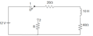
58. In the circuit shown below steady state is obtained before the switch closes at t = 0. The switch is closed for 1.5 s and is then opened. At t = 1 s, V (t) will be?

a) – 3.24 V
b) 1.97 V
c) 5.03 V
d) 13.24 V
Answer: c
Explanation: V (0–) = 10 V = V (0+)
For 0<t≤1.5 s, τ = 4 × 0.05 = 0.2 s
VOC = 5 V
V (t) = 5 + (10 – 5)e−t0.2 = 5 + 5e-5t
V (1s) = 5.03 V.
59. The circuit shown below is at steady state before the switch closes at t=0. The switch is closed for 1.5 s and is then opened. At t = 2 s, V (t) will be?
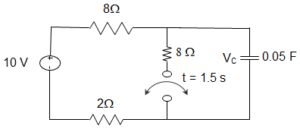
a) 5.12 V
b) 6.43 V
c) 8.57 V
d) 9.88 V
Answer: c
Explanation: V (1.5s) = 5.002 V
For t > 1.5 s, τ = 8 × 0.05 = 0.4
V (t) = 10+ (5-10)e−(t−1.5)0.4 = 10 – 5e-2.5(t-1.5)
For t≥1.5 s, V (2 s) = 8.57 V.
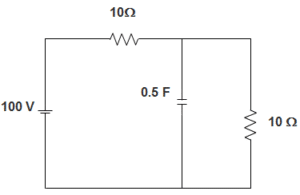
60. In the circuit given below, the voltage across capacitor when switch is closed at t = ∞ is ____________

a) 50 V
b) 20 V
c) 30 V
d) 7.5 V
Answer: a
Explanation: From the figure, we can infer that,
Voltage across capacitor = voltage across 10 Ω resistance.
Now, voltage across the 10 Ω resistance = 10010+10 X 10
= 10020.10
= 50 V.
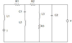
61. In the circuit given below, the current source is 1 A, voltage source is 5 V, R1 = R2 = R3 = 1 Ω, L1 = L2 = L3 = 1 H, C1 = C2 = 1 F. The current through R3 is _________

a) 1 A
b) 5 A
c) 6 A
d) 8 A
Answer: b
Explanation: At steady state, the circuit becomes,
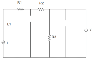
∴ The current through R3 = 51 = 5 A.
62. In the circuit given below, the capacitor is initially having a charge of 10 C. 1 second after the switch is closed, the current in the circuit is ________
a) 14.7 A
b) 18.5 A
c) 40.0 A
d) 50.0 A
Answer: a
Explanation: Using KVL, 100 = Rdqdt+qC
100 C = RCdqdt + q
Or, ∫qqodq100C−q=1RC∫t0dt
100C – q = (100C – qo)e-t/RC
I = dqdt=(100C–qo)RCe−1/1
∴ e-t/RC = 40e-1 = 14.7 A.
63. In the circuit given below, the current source is 1 A, voltage source is 5 V, R1 = R2 = R3 = 1 Ω, L1 = L2 = L3 = 1 H, C1 = C2 = 1 F. The current through the voltage source V is _________
a) 1 A
b) 3 A
c) 2 A
d) 4 A
Answer: d
Explanation: At steady state, the circuit becomes,

∴ The current through the voltage source V = 5 – 1 = 4 A.
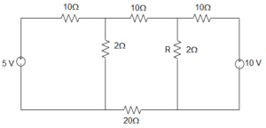
64. In the circuit given below, the voltage across R by mesh analysis is _________
a) 1.59 V
b) 1 V
c) 2.54 V
d) 1.54 V
Answer: d
Explanation: In loop 1, by KVL, (10 + 2) I1 + (-2) I2 + 0I3 = 5
Or, 12 I1 – 2I2 = 5
In loop 2, -2I1 + (10+2+20+2) I2 + (-2) I3 = 0
Or, -2I1 + 34 I2 – 2I3 = 0
In loop 3, 0I1 + – 2I2 + (2+10) I3 = 10
Or, 0I1 – 2I2 + 12I3 = 10
Now, the voltage across R is VR = (I2 – I3) R
Now, I2 = 3604800=340
Now, I3 = 40604800=203240 A
Therefore, VR = (I2 – I3) R = [340–203240]2 = 1.54 V.
65. In a dual slop integrating type digital voltmeter, the firs integrating is carried out for 10 periods of the supply frequency of 50 Hz. If the reference voltage used is 2 V, the total conversion time for an input of 1 V is _________
a) 0.01 s
b) 0.05 s
c) 0.1 s
d) 1 s
Answer: c
Explanation: In a dual slope integrating digital voltmeter,
(t1t2) Vin = Vref
Where, t1 = first integration time = 10 × 150 = 0.25
But Vin = 1 V and Vref = 2 V
∴ t2 = Vint1Vref = 0.1 s.
66. A rectifier type AC voltmeter consists of a series resistance R, an ideal full-wave rectifier bridge and a PMMC instrument. The internal resistance and a full- scale deflection produced by a DC current are 100 Ω and 1 mA respectively. A voltage of 100 V (rms) is applied to the input terminals. The value of R required is _________
a) 63.56 Ω
b) 89.83 Ω
c) 89.83 kΩ
d) 141.3 kΩ
Answer: c
Explanation: VOAverage = 0.636 × 2–√Vrms = 0.8993 Vrms
The deflection with AC is 0.8993 times that with DC for the same value of voltage V
SAC = 0.8993 SDC
SDC of a rectifier type instrument is 1Ifs where Ifs is the current required to produce full scale deflection, Ifs = 1 mA; Rm = 100 Ω; SDC = 103 Ω/V
SAC = 0.8993 × 1000 = 899.3 Ω/V. Resistance of multiplier RS = SAC V – Rm – 2Rd, where Rd is the resistance of diode, for ideal diode Rd = 0
∴ RS = 899.3 × 100 – 100 = 89.83 kΩ.
67. A 1 μF capacitor is connected across a 50 V battery. The battery is kept closed for a long time. The circuit current and voltage across capacitor is __________
a) 0.5 A and 0 V
b) 0 A and 50 V
c) 20 A and 5 V
d) 0.05 A and 5 V
Answer: b
Explanation: We know that, when the capacitor is fully charged, it acts as an open circuit.
That is when the capacitor is fully charged.
So, the circuit current and voltage across capacitor are 0 A and 50 V respectively.
68. In the circuit given below, the switch is closed at t = 0. At t = 0+ the current through C is ___________
a) 2 A
b) 3 A
c) 4 A
d) 5 A
Answer: d
Explanation: We know that,
When the capacitor is fully charged, it acts as a short circuit.
The equivalent resistance Req = (10 + 10) Ω
= 20 Ω
Given voltage = 100 V
So, current through C = 10020 A = 5 A.
69. A digital Multimeter reads 10 V when fed with a triangular wave, which is symmetric about the time-axis. If the input is same, the rms reading meter will read?
a) 203√
b) –103√
c) –203√
d) 103√
Answer: d
Explanation: For triangular wave Average value = Vm3, rms value = Vm3√
∴ Vm3 = 10 V or, Vm = 30 V.
70. A resistance R is measured using the connection shown in the below figure.
The current measured is 10 A on ranges 100A and the voltage measured is 125 V on 150 V range. The scales of the ammeter and voltmeter are uniform. The total number of scale divisions of the ammeter is 100 and that of the voltmeter is 150. The scale division can be distinguished. The constructional error of the ammeter is ± 0.3% and that of voltmeter±0.4%. The resistance of the ammeter is 0.25 Ω. The value of R is _________
a) 12.75 Ω
b) 12.0 Ω
c) 12.25 Ω
d) 12.5 Ω
Answer: c
Explanation: Percentage error in ammeter = ± 110×100 × 100 = ± 0.1%
Percentage error in voltmeter= ±110×150 × 100 = ± 0.067%
So, δI = ± 0.3 ± 0.1 = ± 0.4%
δV = ± 0.4 ± 0.067 = ± 0.467%
R = VI
So, error = ± δV ± δI = ± 0.867
Measured value of resistance = Rm = 12510 = 12.5
∴ True value = Rm(1-RaRm) = 12.25 Ω.
1. The ratio of voltage transform at first port to the voltage transform at the second port is called?
a) Voltage transfer ratio
b) Current transfer ratio
c) Transfer impedance
d) Transfer admittance
Answer: a
Explanation: Voltage transfer ratio is the ratio of voltage transform at first port to the voltage transform at the second port and is denoted by G(s). G21 = V2(s)/V1(s) G12 = V1(s)/V2(s).
2. The ratio of the current transform at one port to current transform at other port is called?
a) Transfer admittance
b) Transfer impedance
c) Current transfer ratio
d) Voltage transfer ratio
Answer: c
Explanation: Current transfer ratio is the ratio of the current transform at one port to current transform at other port and is denoted by α(s). α12(s) = I1(s)/I2(s) α21(s) = I2(s)/I1(s).
3. The ratio of voltage transform at first port to the current transform at the second port is called?
a) Voltage transfer ratio
b) Transfer admittance
c) Current transfer ratio
d) Transfer impedance
Answer: d
Explanation: Transfer impedance is the ratio of voltage transform at first port to the current transform at the second port and is denoted by Z(s). Z21(s) = V2(s)/I1(s) Z12(s) = V1(s)/I2(s).
4. For the network shown in the figure, find the driving point impedance.
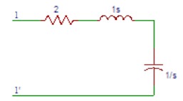
a) (s2-2s+1)/s
b) (s2+2s+1)/s
c) (s2-2s-1)/s
d) (s2+2s-1)/s
Answer: b
Explanation: Applying Kirchoff’s law at port 1, Z(S)=V(S)/I(S), where V(s) is applied at port 1 and I(s) is current flowinmg through the network. Then Z(S)=V(S)/I(S) = 2+S+1/S = (s2+2s+1)/s.
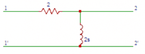
5. Obtain the transfer function G21 (S) in the circuit shown below.
a) (s+1)/s
b) s+1
c) s
d) s/(s+1)
Answer: d
Explanation: Applying Kirchhoff’s law V1 (S) = 2 I1 (S) + 2 sI1 (S) V2 (S) = I1 (S) X 2s Hence G21 (S) = V2(s)/V1(s) =2 s/(2+2 s)=s/(s+1).
6. Determine the transfer function Z21 (S) in the circuit shown in question 5.
a) s
b) 2 s
c) 3 s
d) 4 s
Answer: b
Explanation: The transfer function Z21 (S) is Z21 (S) = V2(S)/I1(S). V2 (S) = I1 (S) X 2s. V2(S)/I1(S)=2s. On substituting Z21 (S) = 2s.
7. Find the driving point impedance Z11 (S) in the circuit shown in question 5.
a) 2(s+2)
b) (s+2)
c) 2(s+1)
d) (s+1)
Answer: c
Explanation: The driving point impedance Z11 (S) is Z11 (S)=V1(S)/I1(S). V1 (S) = 2 I1 (S) + 2 sI1 (S) => V1(S) = (2+2s)I1(S) => V1(S)/I1(S) = 2(s+1). On substituting Z11 (S) = 2(S+1).
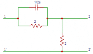
8. Obtain the transfer function G21 (s) in the circuit shown below.
a) (8 S+2)/(8 S+1)
b) (8 S+2)/(8 S+2)
c) (8 S+2)/(8 S+3)
d) (8 S+2)/(8 S+4)
Answer: d
Explanation: From the circuit, the parallel combination of resistance and capacitance can be combined into equivalent in impedance. Zeq(S) = 1/(2 S+1/2)=2/(4 S+1). Applying Kirchhoff’s laws, we have V2 (S) = 2 I1(S) => V1 (S) = I1 (S)[2/(4 S+1)+2] = I1 (S)[(8 S+4)/(4 S+1)] The transfer function G21 (s) = V2(s)/V1(s) =2 I1(S)/((8 S+4)/(4 S+1))I1(S) =(8 S+2)/(8 S+4).
9. Obtain the transfer function Z21(s) in the circuit shown in question 8.
a) 1
b) 2
c) 3
d) 4
Answer: b
Explanation: The transfer function Z21(s) is Z21 (S) = V2(S)/I1(S). V2 (S) = 2 I1(S) => V2 (S)/I1 =2. On substituting Z21(s) = 2.
10. Determine the driving point impedance Z11(S) in the circuit shown in question 8.
a) (8 S+4)/(4 S+4)
b) (8 S+4)/(4 S+3)
c) (8 S+4)/(4 S+2)
d) (8 S+4)/(4 S+1)
Answer: d
Explanation: The driving point impedance Z11(S) is Z11(S) = V1(s)/I1(s). V1(s) = I1(s)((2/(4s+1))+2) = I1(s)((8s+4)/(4s+1)) => V1(s)/I1(s) = ((8s+4)/(4s+1)). On substituting we get Z11(S) = (8S+4)/(4S+1).
11. The coefficients of the polynomials P (S) and Q (S) in the network function N (S) are ________ for passive network.
a) real and positive
b) real and negative
c) complex and positive
d) complex and negative
Answer: a
Explanation: The coefficients of the polynomials P (S) and Q (S) in the network function N (S) are real and positive for passive network. On factorising the network function we obtain the poles and zeros.
12. The scale factor is denoted by the letter?
a) G
b) H
c) I
d) J
Answer: b
Explanation: The scale factor is denoted by the letter ‘H’ and its value is equal to the ratio of ao to bo.
13. The zeros in the transfer function are denoted by?
a) 3
b) 2
c) 1
d) 0
Answer: d
Explanation: The roots of the equation P (S) = 0 are zeros of the transfer function. The zeros in the transfer function are denoted by ‘o’.
14. The poles in the transfer function are denoted by?
a) x
b) y
c) z
d) w
Answer: a
Explanation: The roots of the equation Q (S) = 0 are poles of the transfer function. The poles in the transfer function are denoted by ‘x’.
15. The network function N (S) becomes _________ when s is equal to anyone of the zeros.
a) 1
b) 2
c) 0
d) ∞
Answer: c
Explanation: The network function N (S) becomes zero when s in the transfer function is equal to anyone of the zeros as the network function is completely defined by its poles and zeros.
16. The N (S) becomes ________ when s is equal to any of the poles.
a) ∞
b) 0
c) 1
d) 2
Answer: a
Explanation: The network function is completely defined by its poles and zeros and the network function N (S) becomes infinite when s in the transfer function is equal to anyone of the poles.
17. If the poles or zeros are not repeated, then the function is said to be having __________ poles or ________ zeros.
a) simple, multiple
b) multiple, simple
c) simple, simple
d) multiple, multiple
Answer: c
Explanation: If the poles or zeros are not repeated, then the function is said to be having simple poles or simple zeros and the network function is said to be stable when the real parts of the poles and zeros are negative.
18. If the poles or zeros are repeated, then the function is said to be having __________ poles or ________ zeros.
a) multiple, multiple
b) simple, simple
c) multiple, simple
d) simple, multiple
Answer: a
Explanation: If there are repeated poles or zeros, then function is said to be having multiple poles or multiple zeros and the network function is stable if the poles and zeros lie within the left half of the s-plane.
19. If the number of zeros (n) are greater than the number of poles (m), then there will be _________ number of zeros at s = ∞.
a) n
b) m
c) n-m
d) n+m
Answer: c
Explanation: If the number of zeros (n) are greater than the number of poles (m), then there will be (n-m) number of zeros at s = ∞ and to obtain (n-m) zeros at s = ∞ the condition is n>m.
20. If the number of poles (m)are greater than the number of zeros (n), then there will be _________ number of zeros at s = ∞.
a) m+n
b) m-n
c) m
d) n
Answer: b
Explanation: If the number of poles (m)are greater than the number of zeros (n), then there will be (m-n) number of zeros at s = ∞ and to obtain (m-n) poles at s = ∞ the condition is m>n.
21. The driving point function is the ratio of polynomials in s. Polynomials are obtained from the __________ of the elements and their combinations.
a) transform voltage
b) transform current
c) transform impedance
d) transform admittance
Answer: c
Explanation: The driving point function is the ratio of polynomials in s. Polynomials are obtained from the transform impedance of the elements and their combinations and if the zeros and poles are not repeated then the poles or zeros are said to be distinct or simple.
22. The pole is that finite value of S for which N (S) becomes __________
a) 0
b) 1
c) 2
d) ∞
Answer: d
Explanation: The quantities P1, P2 … Pm are called poles of N (S) if N (S) = ∞ at those points. The pole is that finite value of S for which N (S) becomes infinity.
23. A function N (S) is said to have a pole (or zero) at infinity, if the function N (1/S) has a pole (or zero) at S = ?
a) ∞
b) 2
c) 0
d) 1
Answer: c
Explanation: A function N (S) is said to have a pole (or zero) at infinity, if the function N (1/S) has a pole (or zero) at S = infinity. A zero or pole is said to be of multiplicity ‘r’ if (S-Z)r or(S-P)r is a factor of P(s) or Q(s).
24. The number of zeros including zeros at infinity is __________ the number of poles including poles at infinity.
a) greater than
b) equal to
c) less than
d) greater than or equal to
Answer: b
Explanation: The number of zeros including zeros at infinity is equal to the number of poles including poles at infinity and it cannot be greater than or less than the number of poles including poles at infinity.
25. The poles of driving point impedance are those frequencies corresponding to ___________ conditions?
a) short circuit
b) voltage source
c) open circuit
d) current source
Answer: c
Explanation: A zero of N(s) is a zero of V(s),it signifies a short circuit. Similarly a pole of Z(s) is a zero of I(s). The poles of driving point impedance are those frequencies corresponding to open circuit conditions.
26. The zeros of driving point impedance are those frequencies corresponding to ___________ conditions?
a) current source
b) open circuit
c) voltage source
d) short circuit
Answer: d
Explanation: The zeros of driving point impedance are those frequencies corresponding to short circuit conditions as pole of Z(s) is a zero of I(s) and zero of N(s) is a zero of V(s),it signifies a short circuit.
27. In the driving point admittance function, a zero of Y (s) means a _______of I (S).
a) 1
b) 2
c) 3
d) zero
Answer: d
Explanation: In the driving point admittance function, a zero of Y (s) means a zero of I (S) i.e., the open circuit condition as the driving point admittance function is the ratio of I(s) to V(s).
28. In the driving point admittance function, a pole of Y (s) means a _______ of V (S).
a) zero
b) 1
c) 2
d) 3
Answer: a
Explanation: The driving point admittance function Y(s) = I(s)/V(s). In the driving point admittance function, a pole of Y (s) means a zero of V (S) i.e., the short circuit condition.
29. The real part of all zeros and poles must be?
a) positive or zero
b) negative or zero
c) positive
d) negative
Answer: b
Explanation: The real part of all zeros and poles must be negative or zero. But the poles or zeros should not be positive because if they are positive, then they will lie in the right-half of the s-plane.
30. Poles or zeros lying on the jω axis must be?
a) complex
b) at least one complex pole
c) at least one complex zero
d) simple
Answer: d
Explanation: Poles or zeros lying on the jω axis must be simple because on jω axis the imaginary part of poles or zeros will be zero.
31. The denominator polynomial in a transfer function may not have any missing terms between the highest and the lowest degree, unless?
a) all odd terms are missing
b) all even terms are missing
c) all even or odd terms are missing
d) all even and odd terms are missing
Answer: c
Explanation: All the quotients in the polynomial P(s) are positive. The denominator polynomial in a transfer function may not have any missing terms between the highest and the lowest degree, unless all even or odd terms are missing.For example P(s) = s3+3s is Hurwitz because all quotient terms are positive and all even terms are missing.
32. The roots of the odd and even parts of a Hurwitz polynomial P (s) lie on ____________
a) right half of s plane
b) left half of s-plane
c) on jω axis
d) on σ axis
Answer: c
Explanation: The roots of the odd and even parts of a Hurwitz polynomial P (s) lie on jω axis not on right half of s plane or on left half of s-plane.
33. If the polynomial P (s) is either even or odd, then the roots of P (s) lie on __________
a) on σ axis
b) on jω axis
c) left half of s-plane
d) right half of s plane
Answer: b
Explanation: If the polynomial P (s) is either even or odd, then the roots of P (s) lie on jω axis not on right half of s plane or on left half of s-plane.
34. If the ratio of the polynomial P (s) and its derivative gives a continued fraction expansion with ________ coefficients, then the polynomial P (s) is Hurwitz.
a) all negative
b) all positive
c) positive or negative
d) positive and negative
Answer: b
Explanation: If the ratio of the polynomial P (s) and its derivative P‘(s) gives a continued fraction expansion with all positive coefficients, then the polynomial P (s) is Hurwitz. If all the quotients in the continued fraction expansion are positive, the polynomial P(s) is positive.
35. Consider the polynomial P(s)=s4+3s2+2. The given polynomial P (s) is Hurwitz.
a) True
b) False
Answer: a
Explanation: P(s)=s4+3s2+2 => P‘ (s)=4s3+6s
After doing the continued fraction expansion, we get all the quotients as positive. So, the polynomial P (s) is Hurwitz.
36. When s is real, the driving point impedance function is _________ function and the driving point admittance function is _________ function.
a) real, complex
b) real, real
c) complex, real
d) complex, complex
Answer: b
Explanation: When s is real, the driving point impedance function is real function and the driving point admittance function is real function because the quotients of the polynomials P(s) and Q(s) are real. When Z(s) is determined from the impedances of the individual branches, the quotients are obtained by adding together, multiplying or dividing the branch parameters which are real.
37. The poles and zeros of driving point impedance function and driving point admittance function lie on?
a) left half of s-plane only
b) right half of s-plane only
c) left half of s-plane or on imaginary axis
d) right half of s-plane or on imaginary axis
Answer: c
Explanation: The poles and zeros of driving point impedance function and driving point admittance function lie on left half of s-plane or on imaginary axis of the s-plane..
38. For real roots of sk, all the quotients of s in s2+ωk2 of the polynomial P (s) are __________
a) negative
b) non-negative
c) positive
d) non-positive
Answer: b
Explanation: For real roots of sk, all the quotients of s in s2+ωk2 of the polynomial P (s) are non-negative. So by multiplying all factors in P(s) we find that all quotients are positive.
39. The real parts of the driving point function Z (s) and Y (s) are?
a) positive and zero
b) positive
c) zero
d) positive or zero
Answer: d
Explanation: The real parts of the driving point impedance function Z (s) and driving point admittance function Y (s) are positive or zero.
40. For the complex zeros to appear in conjugate pairs the poles of the network function are ____ and zeros of the network function are ____________
a) complex, complex
b) complex, real
c) real, real
d) real, complex
Answer: c
Explanation: P(s) and Q(s) are real when s is real. So the poles of the network function are real and zeros of the network function are real, the complex zeros to appear in conjugate pairs.
41. The coefficients of numerator polynomial and the denominator polynomial in a transfer function must be?
a) real
b) complex
c) at least one real coefficient
d) at least one complex coefficient
Answer: a
Explanation: The coefficients of P(s), the numerator polynomial and of Q(s), the denominator polynomial in a transfer function must be real. Therefore all poles and zeros if complex must occur in conjugate pairs.
42. In a transfer function, the degree of numerator polynomial is ___________ than the degree of the denominator polynomial.
a) greater than
b) less than
c) equal to
d) less than or equal to
Answer: d
Explanation: In a transfer function, the degree of numerator polynomial is less than or equal to than the degree of the denominator polynomial. And the degree of the numerator polynomial of Z21(s) or Y21(s) is less than or equal to the degree of the denominator polynomial plus one.
43. The real parts of all poles and zeros in a driving point function must be?
a) zero
b) negative
c) zero or negative
d) positive
Answer: c
Explanation: The real parts of all poles and zeros in a driving point function must be zero or negative but should not be positive and the complex or imaginary poles and zeros must occur in conjugate pairs.
44. If the real part of driving point function is zero, then the pole and zero must be?
a) complex
b) simple
c) one complex pole
d) one complex zero
Answer: b
Explanation: If the real part of driving point function is zero, then the pole and zero must be simple but should not contain any complex pole or complex zero.
45. The degree of the numerator polynomial and denominator polynomial in a driving point function may differ by?
a) 0
b) 1
c) 0 or 1
d) 2
Answer: c
Explanation: The degree of numerator polynomial and denominator polynomial in a driving point function may differ by zero or one. And the polynomials P(s) and Q(s) may not have any missing terms between the highest and lowest degrees unless all even or odd terms are missing.
46. The lowest degree in numerator polynomial and denominator polynomial in a driving point function may differ by at most __________
a) 0
b) 1
c) 2
d) 3
Answer: b
Explanation: The lowest degree in numerator polynomial and denominator polynomial in a driving point function may differ by at most one and the coefficients in the polynomials P(s) and Q(s) of network function must be real and positive.
47. The coefficients in the denominator polynomial of the transfer function must be?
a) positive
b) negative
c) positive or zero
d) negative or zero
Answer: a
Explanation: The coefficients in the denominator polynomial of the transfer function must be positive but should not be negative and the coefficients in the polynomials P(s) and Q(s) of transfer function must be real.
48. The coefficients in the numerator polynomial of the transfer function may be?
a) must be negative
b) must be positive
c) may be positive
d) may be negative
Answer: d
Explanation: The coefficients in the numerator polynomial of the transfer function may be negative and the complex or imaginary poles and zeros must occur in conjugate pairs.
49. The denominator polynomial in a transfer function may not have any missing terms between the highest and the lowest degree, unless?
a) all odd terms are missing
b) all even terms are missing
c) all even or odd terms are missing
d) all even and odd terms are missing
Answer: c
Explanation: The denominator polynomial in a transfer function may not have any missing terms between the highest and the lowest degree, unless all even or odd terms are missing and the polynomial P(s) may have missing terms between the lowest and the highest degree.
50. The degree of numerator polynomial in a transfer function may be as small as _________ independent of the degree of the denominator polynomial.
a) 1
b) 2
c) 0
d) 3
Answer: c
Explanation: The degree of numerator polynomial in a transfer function may be as small as zero, independent of the degree of the denominator polynomial and for the voltage transfer ratio and the current transfer ratio, the maximum degree of P(s) must be equal to the degree of Q(s).
51. In the circuit shown below, switch K is moved from position to position 2 at time t = 0. At time t = 0-, the current in the inductor is I0 and the voltage at the capacitor is V0. The inductor is represented by a transform impedance _________ in series with a voltage source __________
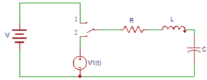
a) Ls, L V0
b) Ls, LI0
c) 1/Ls, LI0
d) 1/Ls, L V0
Answer: a
Explanation: The inductor has an initial current I0. It is represented by a transform impedance Ls in series with a voltage source L V0.
52. In the circuit shown in question 1, the capacitor is replaced by a transform impedance of __________ with an initial voltage ___________
a) 1/Cs, V0/S
b) 1/Cs, I0/S
c) Cs, I0/S
d) Cs, V0/S
Answer: a
Explanation: The capacitor has an initial voltage V0 across it. It is represented by a transform impedance of 1/Cs with an initial voltage V0/S.
53. The value of the total voltage after replacing the inductor and capacitor in question 1 is?
a) V1(S)-LI0-V0/S
b) V1(S)+LI0-V0/S
c) V1(S)+LI0+V0/S
d) V1(S)-LI0+V0/S
Answer: b
Explanation: The current I(s) is given as the total transform voltage in the circuit divided by the total transform impedance. The value of the total voltage after replacing the inductor and capacitor is V (s) = V1(S)+LI0-V0/S.
54. The value of the total impedance after replacing the inductor and capacitor in question 1 is?
a) R-LS-1/CS
b) R-LS+1/CS
c) R+LS+1/CS
d) R+LS-1/CS
Answer: c
Explanation: The value of the total impedance after replacing the inductor and capacitor is
Z (s) = R+LS+1/CS. By knowing the V(s) and Z(s) we can calculate I(s) as I(s) is given as the total transform voltage in the circuit divided by the total transform impedance.
55. The current flowing in the circuit in question 1 is?
a) (V1(S)-LI0-V0/S)/( R+LS+1/CS)
b) (V1(S)-LI0+V0/S)/( R+LS+1/CS)
c) (V1(S)+LI0+V0/S)/( R+LS+1/CS)
d) (V1(S)+LI0-V0/S)/( R+LS+1/CS)
Answer: d
Explanation: The current I(s) is given as the total transform voltage in the circuit divided by the total transform impedance. The current flowing in the circuit is I (s) = V(s)/I(s) =(V1(S)+LI0-V0/S)/( R+LS+1/CS).
56. Obtain the admittance of the last two elements in the parallel combination after transformation in the circuit shown below.
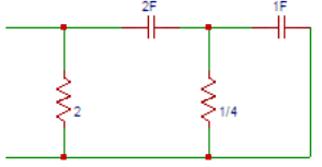
a) 1+s
b) 2+s
c) 3+s
d) 4+s
Answer: d
Explanation: The term admittance is defined as the inverse of impedance. The admittance of capacitor is 1/s and the admittance of resistor is 1/4 mho. So the admittance of the last two elements in the parallel combination is Y1(s) = 4 + s.
57. The impedance of the last two elements in the parallel combination after transformation in the circuit shown in question 6 is?
a) 1/(s+4)
b) 1/(s+3)
c) 1/(s+2)
d) 1/(s+1)
Answer: a
Explanation: The impedance of resistor is 4Ω and the impedance of capacitor is s. So the impedance of the last two elements in the parallel combination is Z1(s) = 1/(s+4).
58. The series combination of the last elements after replacing 1/s and 1/4Ω with 1/(S+4) in the question 6 is?
a) (3s+4)/2s(s-4)
b) (3s-4)/2s(s-4)
c) (3s+4)/2s(s+4)
d) (3s-4)/2s(s+4)
Answer: c
Explanation: We got the impedance of last two elements in parallel combination as Z1(s) = 1/(s+4) and now the impedance of capacitor is 1/2s. So the series combination of the last elements is Z2(s) =1/2s+1/(s+4)=(3s+4)/2s(s+4).
59. Determine the admittance parallel combination of the last elements after replacing with (3s+4)/2s(s+4) in the question 6 is?
a) (4s2-19s+4)/(6s-8)
b) (4s2+19s-4)/(6s+8)
c) (4s2+19s-4)/(6s-8)
d) (4s2+19s+4)/(6s+8)
Answer: d
Explanation: The term admittance is defined as the inverse of the term impedance. As the impedance is Z2(s) =1/2s+1/(s+4)=(3s+4)/2s(s+4) , the admittance parallel combination of the last elements is Y2(s) = 1/2+2s(s+4)/( 3s+4)=(4s2+19s+4)/(6s+8).
60. Obtain the transform impedance of the network shown in question 6.
a) (6s-8)/( 4s2+19s-4)
b) (6s+8)/( 4s2+19s+4)
c) (6s+8)/( 4s2-19s+4)
d) (6s-8)/( 4s2+19s+4)
Answer: b
Explanation: The term impedance is the inverse of the term admittance. We got admittance as Y2(s) = (4s2+19s+4)/(6s+8). So the transform impedance of the network is
Z (s) = 1 / Y2(s) = (6s+8)/( 4s2+19s+4).
1. Two ports containing no sources in their branches are called?
a) active ports
b) passive ports
c) one port
d) three port
Answer: b
Explanation: Two ports containing no sources in their branches are called passive ports; among them are power transmission lines and transformers.
2. Two ports containing sources in their branches are called?
a) three port
b) one port
c) passive ports
d) active ports
Answer: d
Explanation: Two ports containing sources in their branches are called active ports. A voltage and current is assigned to each of the two ports.
3. In determining open circuit impedance parameters, among V1, V2, I1, I2, which of the following are dependent variables?
a) V1 and V2
b) I1 and I2
c) V1 and I2
d) I1 and V2
Answer: a
Explanation: In determining open circuit impedance parameters, among V1, V2, I1, I2; V1 and V2 are dependent variables and I1, I2 are independent variables i.e., dependent variables depend on independent variables.
4. In determining open circuit impedance parameters, among V1, V2, I1, I2, which of the following are independent variables?
a) I1 and V2
b) V1 and I2
c) I1 and I2
d) V1 and V2
Answer: c
Explanation: In determining open circuit impedance parameters, among V1, V2, I1, I2; I1 and I2 are independent variables and V1, V2 are dependent variables. Independent variables are the variables that do not depend on any other variable.
5. Which of the following expression is true in case of open circuit parameters?
a) V1 = Z11 V1 + Z12 I2
b) V1 = Z11I1 + Z12 V2
c) V1 = Z11I1 + Z12 I2
d) V2 = Z11I1 + Z12 I2
Answer: c
Explanation: The expression relating the open circuit parameters Z11, Z12 and currents I1, I2 and voltage V1 is V1 = Z11I1 + Z12 I2.
6. Which of the following expression is true in case of open circuit parameters?
a) V2 = Z21I2 + Z22 I2
b) V2 = Z21I1 + Z22 I2
c) V1 = Z21I2 + Z22 I2
d) V1 = Z21I1 + Z22 I2
Answer: b
Explanation: The expression relating the currents I1, I2 and voltage V1 and open circuit parameters Z21, Z22 is V2 = Z21I1 + Z22 I2.
7. Find the Z – parameter Z11 in the circuit shown below.
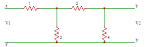
a) 1
b) 1.5
c) 2
d) 2.5
Answer: d
Explanation: For determining Z11, the current I2 is equal to zero. Now we obtain Zeq as 1+ (6×2)/(6+2)=2.5Ω. So, Z11 = 2.5Ω.
8. The value of Z21 in the circuit shown in the question 7 is?
a) 0
b) 1
c) 2
d) 3
Answer: b
Explanation: V2 is the voltage across the 4Ω impedance. The current through 4Ω impedance is I1/4. And V2 = (I1/4) x 4 = I1. So, Z21 = 1Ω.
9. Find the value of Z12 in the circuit shown in the question 7.
a) 3
b) 2
c) 1
d) 0
Answer: c
Explanation: The current through vertical 2Ω resistor is = I2/2. So, V1 = 2 x (I2/2). On solving and substituting we get Z12 = 1Ω.
10. Determine the value of Z22 in the circuit shown in the question 7.
a) 0
b) 1
c) 2
d) 3
Answer: c
Explanation: Open circuiting port 1, we get V2 = I2((2+2)||4) => V2 = I2 x 2 =>V2/I2 = 2. Therefore the value of Z22 is 2Ω.
11. In determining short circuit impedance parameters, among V1, V2, I1, I2, which of the following are dependent variables?
a) V1 and V2
b) I1 and I2
c) V1 and I2
d) I1 and V2
Answer: b
Explanation: In determining short circuit impedance parameters, among V1, V2, I1, I2; I1 and I2 are dependent variables and V1, V2 are independent variables i.e., dependent variables depend on independent variables.
12. In determining short circuit impedance parameters, among V1, V2, I1, I2, which of the following are independent variables?
a) I1 and V2
b) V1 and I2
c) I1 and I2
d) V1 and V2
Answer: d
Explanation: In determining short circuit impedance parameters, among V1, V2, I1, I2; V1 and V2 are independent variables and I1, I2 are dependent variables. Independent variables are the variables that do not depend on any other variable.
13. Which of the following expression is true in case of short circuit parameters?
a) I1 = Y11 V1 + Y12 V2
b) I1 = Y11 I1 + Y12 V2
c) V1 = Y11 I1 + Y12 V2
d) V1 = Y11 V1 + Y12 V2
Answer: a
Explanation: The expression relating the short circuit parameters Y11, Y12 and voltages V1, V2 and current is I1, is I1 = Y11 V1 + Y12 V2.
14. Which of the following expression is true in case of short circuit parameters?
a) I2 = Y21I1 + Y22 I2
b) V2 = Y21I1 + Y22 V2
c) I2 = Y21V1 + Y22 V2
d) I2 = Y21V1 + Y22 I2
Answer: c
Explanation: The expression relating the voltages V1, V2 and current is I2 and short circuit parameters Y11, Y12 is I2 = Y21V1 + Y22V2.
15. The parameters Y11, Y12, Y21, Y22 are called?
a) Open circuit impedance parameters
b) Short circuit admittance parameters
c) Inverse transmission parameters
d) Transmission parameters
Answer: b
Explanation: The parameters Y11, Y12, Y21, Y22 are called short circuit admittance parameters also called network functions as they are obtained by short circuiting port 1 or port 2.
16. Find the Y – parameter Y11 in the circuit shown below.
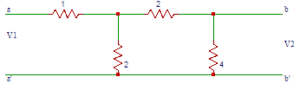
a) 2
b) 3/2
c) 1
d) 1/2
Answer: d
Explanation: After short circuiting b-b’, the equation will be V1 = (I1) x 2. We know Y11 = I1/V1. From the equation we get I1/V1 = 2. On substituting we get Y11 = 2 mho.
17. Find the Y – parameter Y21 in the circuit shown in question 6.
a) -1/4
b) 1/4
c) 1/2
d) -1/2
Answer: a
Explanation: After short circuiting b-b’, the equation will be -I2=I1 × 2/4=I1/2 and -I2= V1/4 and on solving and substituting we get Y21 =I2/V1=-1/4 mho.
18. Find the Y – parameter Y22 in the circuit shown in question 6.
a) 3/8
b) 5/8
c) 7/8
d) 9/8
Answer: b
Explanation: On short circuiting a-a’,we get Zeq = 8/5 Ω. V2=I2× 8/5. We know Y22 = I2/V2. We got I2/V1 = 5/8. ON substituting we get Y22 = 5/8 mho.
19. Find the Y – parameter Y12 in the circuit shown in question 6.
a) 1/2
b) -1/2
c) -1/4
d) 1/4
Answer: c
Explanation: Short circuiting a-a’, -I1= 2/5 I2 and I2= 5 V2/8. On solving -I1= 2/5×5/8 V2= V2/4. We know
Y12 = I1/V2. We got I1/V2 = -1/4. So the value of Y12 will be -1/4 mho.
20. Which of the following equation is true in the circuit shown in question 6?
a) I1=0.5(V1)+0.25(V2)
b) I1=0.25(V1)+0.625(V2)
c) I1=-0.25(V1)+0.625(V2)
d) I1=0.5(V1)-0.25(V2)
Answer: d
Explanation: We got the admittance parameters as Y11 = 0.5, Y12 = -0.25, Y21 = -0.25, Y22 = 0.625. So the equations in terms of admittance parameters is
I1=0.5(V1)-0.25(V2) and I2=-0.25(V1)+0.625(V2).
21.In the circuit shown below, find the transmission parameter A.
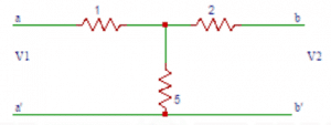
a) 6/5
b) 5/6
c) 3/4
d) 4/3
Answer: a
Explanation: Open circuiting b-b‘, V1 = 6 I1, V2 = 5I1. On solving V1/V2 = 6/5. On substituting we get A = V1/V2=6/5.
22. In the circuit shown above, find the transmission parameter C.
a) 4/5
b) 3/5
c) 2/5
d) 1/5
Answer: d
Explanation: C = I1/V2 |I2=0. By open circuiting b-b‘ we get V2 = 5 I1 =>I1/V2 = 1/5. On substituting we get C = I1/V2=1/5 Ω.
23. In the circuit shown above, find the transmission parameter B.
a) 15/5
b) 17/5
c) 19/5
d) 21/5
Answer: b
Explanation: The transmission parameter B is given by B = -V1/I2 |V2=0. Short circuiting b-b‘, -I2= 5/17 V1 => -V1/I2 = 17/5. On substituting we get B=17/5 Ω.
24. In the circuit shown above, find the transmission parameter D.
a) 1/5
b) 3/5
c) 7/5
d) 9/5
Answer: c
Explanation: D is a transmission parameter and is given by D = -I1/I2 |V2=0. Short circuiting b-b‘, I1= 7/17 V1 and-I2= 5/17 V1. So we get I1/I2 = 7/5. So D=7/5.
25. The hybrid parameter h11 is called?
a) short circuit input impedance
b) short circuit forward current gain
c) open circuit reverse voltage gain
d) open circuit output admittance
Answer: a
Explanation: h11=V1/I1 |V2=0. So the hybrid parameter h11 is called short circuit input impedance.
26. The hybrid parameter h21 is called?
a) open circuit output admittance
b) open circuit reverse voltage gain
c) short circuit forward current gain
d) short circuit input impedance
Answer: c
Explanation: h21=I2/I1 |V2=0. So the hybrid parameter h21 is called short circuit forward current gain.
27. In the circuit shown below, find the h-parameter h11.
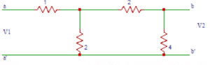
a) 1
b) 2
c) 3
d) 4
Answer: b
Explanation: h11=V1/I1 |V2=0. So short circuiting b-b‘, V1 = I1((2||2)+1) = 2I1 => V1/I1= 2. On substituting we get h11 = V1/I1= 2Ω.
28. In the circuit shown in question 7, find the h-parameter h21.
a) 1
b) -1
c) 1/2
d) -1/2
Answer: d
Explanation: Short circuiting b-b‘, h21 = I2/I1 when V2=0 and -I2= I1/2 => I2/I1 = -1/2. So h21 = -1/2.
29. In the circuit shown in question 7, find the h-parameter h12.
a) 1/2
b) -1/2
c) 1
d) -1
Answer: a
Explanation: Open circuiting a-a‘ we get V1=Iy×2 and
Iy=I2/2 and V2=Ix×4 and Ix=I2/2. On solving and substituting, we get h12 =V1/V2=1/2.
30. In the circuit shown in question 7, find the h-parameter h22.
a) 1
b) 2
c) 1/2
d) 3/2
Answer: c
Explanation: Open circuiting a-a‘ we get V1=Iy×2 and Iy=I2/2 and V2=Ix×4 and Ix=I2/2. On solving and substituting, we get h22 =I2/V2=1/2 Ω.
31. The denominator polynomial in a transfer function may not have any missing terms between the highest and the lowest degree, unless?
a) all odd terms are missing
b) all even terms are missing
c) all even or odd terms are missing
d) all even and odd terms are missing
Answer: c
Explanation: All the quotients in the polynomial P(s) are positive. The denominator polynomial in a transfer function may not have any missing terms between the highest and the lowest degree, unless all even or odd terms are missing.For example P(s) = s3+3s is Hurwitz because all quotient terms are positive and all even terms are missing.
32. The roots of the odd and even parts of a Hurwitz polynomial P (s) lie on ____________
a) right half of s plane
b) left half of s-plane
c) on jω axis
d) on σ axis
Answer: c
Explanation: The roots of the odd and even parts of a Hurwitz polynomial P (s) lie on jω axis not on right half of s plane or on left half of s-plane.
33. If the polynomial P (s) is either even or odd, then the roots of P (s) lie on __________
a) on σ axis
b) on jω axis
c) left half of s-plane
d) right half of s plane
Answer: b
Explanation: If the polynomial P (s) is either even or odd, then the roots of P (s) lie on jω axis not on right half of s plane or on left half of s-plane.
34. If the ratio of the polynomial P (s) and its derivative gives a continued fraction expansion with ________ coefficients, then the polynomial P (s) is Hurwitz.
a) all negative
b) all positive
c) positive or negative
d) positive and negative
Answer: b
Explanation: If the ratio of the polynomial P (s) and its derivative P‘(s) gives a continued fraction expansion with all positive coefficients, then the polynomial P (s) is Hurwitz. If all the quotients in the continued fraction expansion are positive, the polynomial P(s) is positive.
35. Consider the polynomial P(s)=s4+3s2+2. The given polynomial P (s) is Hurwitz.
a) True
b) False
Answer: a
Explanation: P(s)=s4+3s2+2 => P‘ (s)=4s3+6s
After doing the continued fraction expansion, we get all the quotients as positive. So, the polynomial P (s) is Hurwitz.
36. When s is real, the driving point impedance function is _________ function and the driving point admittance function is _________ function.
a) real, complex
b) real, real
c) complex, real
d) complex, complex
Answer: b
Explanation: When s is real, the driving point impedance function is real function and the driving point admittance function is real function because the quotients of the polynomials P(s) and Q(s) are real. When Z(s) is determined from the impedances of the individual branches, the quotients are obtained by adding together, multiplying or dividing the branch parameters which are real.
37. The poles and zeros of driving point impedance function and driving point admittance function lie on?
a) left half of s-plane only
b) right half of s-plane only
c) left half of s-plane or on imaginary axis
d) right half of s-plane or on imaginary axis
Answer: c
Explanation: The poles and zeros of driving point impedance function and driving point admittance function lie on left half of s-plane or on imaginary axis of the s-plane..
38. For real roots of sk, all the quotients of s in s2+ωk2 of the polynomial P (s) are __________
a) negative
b) non-negative
c) positive
d) non-positive
Answer: b
Explanation: For real roots of sk, all the quotients of s in s2+ωk2 of the polynomial P (s) are non-negative. So by multiplying all factors in P(s) we find that all quotients are positive.
39. The real parts of the driving point function Z (s) and Y (s) are?
a) positive and zero
b) positive
c) zero
d) positive or zero
Answer: d
Explanation: The real parts of the driving point impedance function Z (s) and driving point admittance function Y (s) are positive or zero.
40. For the complex zeros to appear in conjugate pairs the poles of the network function are ____ and zeros of the network function are ____________
a) complex, complex
b) complex, real
c) real, real
d) real, complex
Answer: c
Explanation: P(s) and Q(s) are real when s is real. So the poles of the network function are real and zeros of the network function are real, the complex zeros to appear in conjugate pairs.
41.In the circuit shown below, find the Z-parameter Z11.
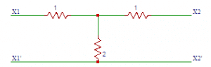
a) 1
b) 2
c) 3
d) 4
Answer: c
Explanation: The Z –parameter Z11 is V1/I1, port 2 is open circuited. V1 = (1+2)I1 => V1/I1 = 3 and on substituting, we get Z11 = 3Ω.
42. In the circuit shown in question 1, find the Z-parameter Z12.
a) 4
b) 3
c) 2
d) 1
Answer: c
Explanation: The Z-parameter Z12 is V2/I1 |I2=0. On open circuiting port 2 we obtain the equation, V1 = (2) I2 => V1/I1 = 2. On substituting we get Z12 = 2Ω.
43. In the circuit shown in question 1, find the Z-parameter Z21.
a) 2
b) 4
c) 1
d) 3
Answer: a
Explanation: The Z-parameter Z21 is V2/I1 |I2=0. On open circuiting port 2, we get V2 = (2)I1 => V2/I1 = 2. On substituting we get Z21 = 2Ω.
44. In the circuit shown in question 1, find the Z-parameter Z22.
a) 3
b)2
c) 4
d) 1
Answer: a
Explanation: The Z-parameter Z21 is V2/I2 |I1=0. This parameter is obtained by open circuiting port 1. So we get V2 = (2 + 1)I2 => V2 = 3(I2) => V2/I2 = 3. On substituting Z21 = 3Ω.
45. In the circuit shown below, find the Z-parameter Z11.
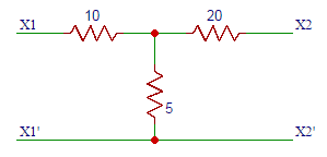
a) 10
b) 15
c) 20
d) 25
Answer: b
Explanation: The Z –parameter Z11 is V1/I1, port 2 is open circuited. V1 = (10 + 5)I1 => V1/I1 = 15 and on substituting, we get Z11 = 2.5Ω.
46. In the circuit shown in question 5, find the Z-parameter Z12.
a) 15
b) 10
c) 5
d) 1
Answer: c
Explanation: The Z-parameter Z12 is V2/I1 |I2=0. On open circuiting port 2 we obtain the equation, V1 = (5) I2 => V1/I1 = 5. On substituting we get Z12 = 5Ω.
47. From the circuits shown in question 1 in question 5, find the combined Z-parameter Z11.
a) 8
b) 18
c) 28
d) 38
Answer: b
Explanation: The Z-parameter Z11 is Z11 = Z11x + Z11y and Z11x = 3, Z11y = 15. On substituting we get Z11 = 3 +15 = 18Ω.
48. From the circuits shown in question 1 in question 5, find the combined Z-parameter Z12.
a) 4
b) 5
c) 6
d) 7
Answer: d
Explanation: The Z-parameter Z12 is Z12 = Z12x + Z12y and we have Z12x = 2, Z12y. On substituting we get Z12 = 2 + 5 = 7Ω.
49. From the circuits shown in question 1 in question 5, find the combined Z-parameter Z21.
a) 7
b) 6
c) 5
d) 4
Answer: a
Explanation: The Z-parameter Z21 is Z21 = Z21x + Z21y and we have Z21x = 2, Z21y = 5. On substituting we get Z21 = 2 + 5 = 7Ω.
50. From the circuits shown in question 1 in question 5, find the combined Z-parameter Z22.
a) 38
b) 28
c) 18
d) 8
Answer: b
Explanation: The Z-parameter Z22 is Z22 = Z22x + Z22y and we have Z22x = 3, Z22y = 25. On substituting we get Z22 = 3 +25 = 28Ω.
51. A periodic voltage v (t) = 1 + 4 sin ωt + 2 cos ωt is applied across a 1Ω resistance. The power dissipated is ____________
a) 1 W
b) 11 W
c) 21 W
d) 24.5 W
Answer: b
Explanation: Given that, v (t) = 1 + 4 sin ωt + 2 cos ωt
So, Power is given by,
Power, P = 121+422√1+222√1
= 11 W.
52. A constant k high pass p section has a characteristic impedance of 300 Ω at f = ∞. At f = fc, the characteristic impedance will be?
a) 0
b) ∞
c) 300 Ω
d) More than 300 Ω
Answer: b
Explanation: For constant k high pass p section is given by,
Z = R1–(fdf)2√
At f = fd, denominator term is 0.
So, Z = infinite.
53. In the circuit given below, the current through R is 2 sin 8t. The value of R is ___________
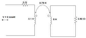
a) (0.18 + j0.72)
b) (0.46 + j1.90)
c) – (0.18 + j1.90)
d) (0.23 – 0.35 j)
Answer: d
Explanation: Here, Inductor is not given, hence ignoring the inductance. Let I1 and I2 are currents in the loop then,
I1 = 2sin8t3
= 0.66 sin 8t
Again, I2 = −jX4X0.75I13.92−2.56j
= (0.23 – 0.35j) sin 8t
So, R = (0.23 – 0.35 j).
54. For a T-network if the Short circuit admittance parameters are given as y11, y21, y12, y22, then y21 in terms of Hybrid parameters can be expressed as ________
a) y21 = (−h21h12h11+h22)
b) y21 = h21h11
c) y21 = –h12h11
d) y21 = 1h11
Answer: b
Explanation: We know that, I1 = y11 V1 + y12 V2 ……… (1)
I2 = y21 V1 + y22 V2 ………. (2)
And, V1 = h11 I1 + h12 V2 ………. (3)
I2 = h21 I1 + h22 V2 ……….. (4)
Now, (3) and (4) can be rewritten as,
I1 = V1h11–h12V2h11 ………. (5)
And I2 = h21V1h11+(−h21h12h11+h22)V2 ………. (6)
∴ Comparing (1), (2) and (5), (6), we get,
y11 = 1h11
y12 = –h12h11
y21 = h21h11
y22 = (−h21h12h11+h22).
55. For a T-network if the Open circuit impedance parameters are given as z11, z21, z12, z22, then z21 in terms of Hybrid parameters can be expressed as ________
a) z21 = (h11–h21h12h22)
b) z21 = – h21h22
c) z21 = h12h22
d) z21 = 1h22
Answer: b
Explanation: We know that, V1 = z11 I1 + z12 I2 ……… (1)
V2 = z21 I1 + z22 I2 ………. (2)
And, V1 = h11 I1 + h12 V2 ………. (3)
I2 = h21 I1 + h22 V2 ……….. (4)
Now, (3) and (4) can be rewritten as,
V1 = (h11–h21h12h22)I1+h12h22I2 ………… (5)
And V2 = I2h22–h21I1h22 ……….. (6)
∴ Comparing (1), (2) and (5), (6), we get,
z11 = (h11–h21h12h22)
z12 = h12h22
z21 = – h21h22
z22 = 1h22.
56. For a T-network if the Open circuit impedance parameters are given as z11, z21, z12, z22, then z11 in terms of Hybrid parameters can be expressed as ________
a) z11 = (h11–h21h12h22)
b) z11 = – h21h22
c) z11 = h12h22
d) z11 = 1h22
Answer: a
Explanation: We know that, V1 = z11 I1 + z12 I2 ……… (1)
V2 = z21 I1 + z22 I2 ………. (2)
And, V1 = h11 I1 + h12 V2 ………. (3)
I2 = h21 I1 + h22 V2 ……….. (4)
Now, (3) and (4) can be rewritten as,
V1 = (h11–h21h12h22)I1+h12h22I2 ………… (5)
And V2 = I2h22–h21I1h22 ……….. (6)
∴ Comparing (1), (2) and (5), (6), we get,
z11 = (h11–h21h12h22)
z12 = h12h22
z21 = – h21h22
z22 = 1h22.
57. For a T-network if the Open circuit impedance parameters are given as z11, z21, z12, z22, then z12 in terms of Hybrid parameters can be expressed as ________
a) z12 = (h11–h21h12h22)
b) z12 = – h21h22
c) z12 = h12h22
d) z12 = 1h22
Answer: c
Explanation: We know that, V1 = z11 I1 + z12 I2 ……… (1)
V2 = z21 I1 + z22 I2 ………. (2)
And, V1 = h11 I1 + h12 V2 ………. (3)
I2 = h21 I1 + h22 V2 ……….. (4)
Now, (3) and (4) can be rewritten as,
V1 = (h11–h21h12h22)I1+h12h22I2 ………… (5)
And V2 = I2h22–h21I1h22 ……….. (6)
∴ Comparing (1), (2) and (5), (6), we get,
z11 = (h11–h21h12h22)
z12 = h12h22
z21 = – h21h22
z22 = 1h22.
58. For a T-network if the Open circuit impedance parameters are given as z11, z21, z12, z22, then z22 in terms of Hybrid parameters can be expressed as ________
a) z22 = (h11–h21h12h22)
b) z22 = – h21h22
c) z22 = h12h22
d) z22 = 1h22
Answer: d
Explanation: We know that, V1 = z11 I1 + z12 I2 ……… (1)
V2 = z21 I1 + z22 I2 ………. (2)
And, V1 = h11 I1 + h12 V2 ………. (3)
I2 = h21 I1 + h22 V2 ……….. (4)
Now, (3) and (4) can be rewritten as,
V1 = (h11–h21h12h22)I1+h12h22I2 ………… (5)
And V2 = I2h22–h21I1h22 ……….. (6)
∴ Comparing (1), (2) and (5), (6), we get,
z11 = (h11–h21h12h22)
z12 = h12h22
z21 = – h21h22
z22 = 1h22.
59. Permeability is analogous to _____________
a) Conductivity
b) Resistivity
c) Retentivity
d) Coercivity
Answer: a
Explanation: We know that resistance and reluctance are given by,
R = ρLA
And Reluctance = LμA
So, Permeability is analogous to conductivity.
60. A resistance and an inductance are connected in parallel and fed from 50 Hz ac mains. Each branch takes a current of 5 A. The current supplied by source is ____________
a) 10 A
b) 7.07 A
c) 5 A
d) 0 A
Answer: b
Explanation: The current is given by,
|5 – j5| = 52+52−−−−−−√
= 50−−√=52–√ = 7.07 A.
61. A triangular Pulse of 50 V peak is applied to a capacitor of 0.1 F. The change of the capacitor and its waveform shape is ___________
a) 10 rectangular
b) 5 rectangular
c) 5 triangular
d) 10 triangular
Answer: c
Explanation: We know that,
Q = CV
Or, 0.1 X 50 = 5
And it is a triangular pulse.
62. A 10 μF capacitor is charged from a 5 volt source through a resistance of 10 kΩ. The charging current offer 35 m sec. If the initial voltage on C is – 3 V is ___________
a) 0.56 mA
b) 5.6 mA
c) 6 mA
d) 5 μA
Answer: a
Explanation: Initial current immediately after charging is given by,
VR=5+310000
= 0.8 mA
Now, i = i0e-t/RC
= 0.8 mA x et10kX10X10−6
= 0.8 X 10⁻³ X e35X10−310−1
= 0.56 mA.
63. For a T-network if the Open circuit impedance parameters are given as z11, z21, z12, z22, then z11 in terms of Inverse Hybrid parameters can be expressed as ________
a) z12 = 1g11
b) z12 = – g12g11
c) z12 = – g21g11
d) z12 = (g22–g21g12g11)
Answer: a
Explanation: We know that, V1 = z11 I1 + z12 I2 ……… (1)
V2 = z21 I1 + z22 I2 ………. (2)
And, I1 = g11 V1 + g12 I2 ………. (3)
V2 = g21 V1 + g22 I2 ……….. (4)
Now, (3) and (4) can be rewritten as,
V1 = I1g11–g12g11I2 ………… (5)
And V2 = (g22–g21g12g11)I2–g21I1g11 ……….. (6)
∴ Comparing (1), (2) and (5), (6), we get,
z11 = 1g11
z12 = – g12g11
z21 = – g21g11
z22 = (g22–g21g12g11).
64. For a T-network if the Open circuit impedance parameters are given as z11, z21, z12, z22, then z12 in terms of Inverse Hybrid parameters can be expressed as ________
a) z12 = 1g11
b) z12 = – g12g11
c) z12 = – g21g11
d) z12 = (g22–g21g12g11)
Answer: b
Explanation: We know that, V1 = z11 I1 + z12 I2 ……… (1)
V2 = z21 I1 + z22 I2 ………. (2)
And, I1 = g11 V1 + g12 I2 ………. (3)
V2 = g21 V1 + g22 I2 ……….. (4)
Now, (3) and (4) can be rewritten as,
V1 = I1g11–g12g11I2 ………… (5)
And V2 = (g22–g21g12g11)I2–g21I1g11 ……….. (6)
∴ Comparing (1), (2) and (5), (6), we get,
z11 = 1g11
z12 = – g12g11
z21 = – g21g11
z22 = (g22–g21g12g11).
65. For a T-network if the Open circuit impedance parameters are given as z11, z21, z12, z22, then z22 in terms of Inverse Hybrid parameters can be expressed as ________
a) z22 = 1g11
b) z22 = – g12g11
c) z22 = – g21g11
d) z22 = (g22–g21g12g11)
Answer: d
Explanation: We know that, V1 = z11 I1 + z12 I2 ……… (1)
V2 = z21 I1 + z22 I2 ………. (2)
And, I1 = g11 V1 + g12 I2 ………. (3)
V2 = g21 V1 + g22 I2 ……….. (4)
Now, (3) and (4) can be rewritten as,
V1 = I1g11–g12g11I2 ………… (5)
And V2 = (g22–g21g12g11)I2–g21I1g11 ……….. (6)
∴ Comparing (1), (2) and (5), (6), we get,
z11 = 1g11
z12 = – g12g11
z21 = – g21g11
z22 = (g22–g21g12g11).
66. For a T shaped network, if the Short-circuit admittance parameters are y11, y12, y21, y22, then y11 in terms of Transmission parameters can be expressed as ________
a) y11 = DB
b) y11 = C−AB
c) y11 = – 1B
d) y11 = AB
Answer: a
Explanation: We know that, V1 = AV2 – BI2 ……… (1)
I1 = CV2 – DI2 …………… (2)
And, I1 = y11 V1 + y12 V2 ……… (3)
I2 = y21 V1 + y22 V2 ………. (4)
Now, (1) and (2) can be rewritten as, I2 = ABV2–1BV1 …………. (5)
And I1 = CV2 – D (ABV2–1BV1)=DBV1+(C−AB)V2 …………… (6)
Comparing equations (3), (4) and (5), (6), we get,
y11 = DB
y12 = C−AB
y21 = – 1B
y22 = AB.
67. For a T shaped network, if the Short-circuit admittance parameters are y11, y12, y21, y22, then y12 in terms of Transmission parameters can be expressed as ________
a) y12 = DB
b) y12 = C−AB
c) y12 = – 1B
d) y12 = AB
Answer: b
Explanation: We know that, V1 = AV2 – BI2 ……… (1)
I1 = CV2 – DI2 …………… (2)
And, I1 = y11 V1 + y12 V2 ……… (3)
I2 = y21 V1 + y22 V2 ………. (4)
Now, (1) and (2) can be rewritten as, I2 = ABV2–1BV1 …………. (5)
And I1 = CV2 – D (ABV2–1BV1)=DBV1+(C−AB)V2 …………… (6)
Comparing equations (3), (4) and (5), (6), we get,
y11 = DB
y12 = C−AB
y21 = – 1B
y22 = AB.
68. For a T shaped network, if the Short-circuit admittance parameters are y11, y12, y21, y22, then y21 in terms of Transmission parameters can be expressed as ________
a) Y21 = DB
b) Y21 = C−AB
c) Y21 = – 1B
d) Y21 = AB
Answer: c
Explanation: We know that, V1 = AV2 – BI2 ……… (1)
I1 = CV2 – DI2 …………… (2)
And, I1 = y11 V1 + y12 V2 ……… (3)
I2 = y21 V1 + y22 V2 ………. (4)
Now, (1) and (2) can be rewritten as, I2 = ABV2–1BV1 …………. (5)
And I1 = CV2 – D (ABV2–1BV1)=DBV1+(C−AB)V2 …………… (6)
Comparing equations (3), (4) and (5), (6), we get,
y11 = DB
y12 = C−AB
y21 = – 1B
y22 = AB.
69. For a T shaped network, if the Short-circuit admittance parameters are y11, y12, y21, y22, then y22 in terms of Transmission parameters can be expressed as ________
a) y22 = DB
b) y22 = C−AB
c) y22 = – 1B
d) y22 = AB
Answer: d
Explanation: We know that, V1 = AV2 – BI2 ……… (1)
I1 = CV2 – DI2 …………… (2)
And, I1 = y11 V1 + y12 V2 ……… (3)
I2 = y21 V1 + y22 V2 ………. (4)
Now, (1) and (2) can be rewritten as, I2 = ABV2–1BV1 …………. (5)
And I1 = CV2 – D (ABV2–1BV1)=DBV1+(C−AB)V2 …………… (6)
Comparing equations (3), (4) and (5), (6), we get,
y11 = DB
y12 = C−AB
y21 = – 1B
y22 = AB.
70. For a T-network if the Open circuit Impedance parameters are z11, z12, z21, z22, then z11 in terms of Transmission parameters can be expressed as ____________
a) z11 = AC
b) z11 = ADC–B
c) z11 = 1C
d) z11 = DC
Answer: a
Explanation: We know that, V1 = z11 I1 + z12 I2 …………. (1)
V2 = z21 I1 + z22 I2 ……………. (2)
And V1 = AV2 – BI2 ……… (3)
I1 = CV2 – DI2 …………… (4)
Rewriting (3) and (4), we get,
V2 = 1CI1+DCI2 …………… (5)
And V1 = A(1CI1+DCI2)–BI2=ACI1+(ADC–B)I2 ………….. (6)
Comparing (1), (2) and (5), (6), we get,
z11 = AC
z12 = ADC–B
z21 = 1C
z22 = DC.
71. For a T-network if the Open circuit Impedance parameters are z11, z12, z21, z22, then z12 in terms of Transmission parameters can be expressed as ____________
a) z12 = AC
b) z12 = ADC–B
c) z12 = 1C
d) z12 = DC
Answer: b
Explanation: We know that, V1 = z11 I1 + z12 I2 …………. (1)
V2 = z21 I1 + z22 I2 ……………. (2)
And V1 = AV2 – BI2 ……… (3)
I1 = CV2 – DI2 …………… (4)
Rewriting (3) and (4), we get,
V2 = 1CI1+DCI2 …………… (5)
And V1 = A(1CI1+DCI2)–BI2=ACI1+(ADC–B)I2 ………….. (6)
Comparing (1), (2) and (5), (6), we get,
z11 = AC
z12 = ADC–B
z21 = 1C
z22 = DC.
72. For a T-network if the Open circuit Impedance parameters are z11, z12, z21, z22, then z21 in terms of Transmission parameters can be expressed as ____________
a) z21 = AC
b) z21 = ADC–B
c) z21 = 1C
d) z21 = DC
Answer: c
Explanation: We know that, V1 = z11 I1 + z12 I2 …………. (1)
V2 = z21 I1 + z22 I2 ……………. (2)
And V1 = AV2 – BI2 ……… (3)
I1 = CV2 – DI2 …………… (4)
Rewriting (3) and (4), we get,
V2 = 1CI1+DCI2 …………… (5)
And V1 = A(1CI1+DCI2)–BI2=ACI1+(ADC–B)I2 ………….. (6)
Comparing (1), (2) and (5), (6), we get,
z11 = AC
z12 = ADC–B
z21 = 1C
z22 = DC.
73. For a T-network if the Open circuit Impedance parameters are z11, z12, z21, z22, then z22 in terms of Transmission parameters can be expressed as ____________
a) z22 = AC
b) z22 = ADC–B
c) z22 = 1C
d) z22 = DC
Answer: d
Explanation: We know that, V1 = z11 I1 + z12 I2 …………. (1)
V2 = z21 I1 + z22 I2 ……………. (2)
And V1 = AV2 – BI2 ……… (3)
I1 = CV2 – DI2 …………… (4)
Rewriting (3) and (4), we get,
V2 = 1CI1+DCI2 …………… (5)
And V1 = A(1CI1+DCI2)–BI2=ACI1+(ADC–B)I2 ………….. (6)
Comparing (1), (2) and (5), (6), we get,
z11 = AC
z12 = ADC–B
z21 = 1C
z22 = DC.
74. For a T shaped network, if the Short-circuit admittance parameters are y11, y12, y21, y22, then y11 in terms of Inverse Transmission parameters can be expressed as ________
a) y11 = A′B′
b) y11 = – 1B′
c) y11 = (C′–D′A′B′)
d) y11 = D′B′
Answer: a
Explanation: We know that, V2 = A’V1 – B’I1 ……… (1)
I2 = C’V1 – D’I1 …………… (2)
And, I1 = y11 V1 + y12 V2 ……… (3)
I2 = y21 V1 + y22 V2 ………. (4)
Now, (1) and (2) can be rewritten as, I1 = – 1B′V2+A′B′V1 …………. (5)
And I2 = C’V1 – D’ (−1B′V2+A′B′V1)=(C′–D′A′B′)V1+D′B′V2 ………… (6)
Comparing equations (3), (4) and (5), (6), we get,
y11 = A′B′
y12 = – 1B′
y21 = (C′–D′A′B′)
y22 = D′B′.
75. For a T shaped network, if the Short-circuit admittance parameters are y11, y12, y21, y22, then y12 in terms of Inverse Transmission parameters can be expressed as ________
a) y12 = A′B′
b) y12 = – 1B′
c) y12 = (C′–D′A′B′)
d) y12 = D′B′
Answer: b
Explanation: We know that, V2 = A’V1 – B’I1 ……… (1)
I2 = C’V1 – D’I1 …………… (2)
And, I1 = y11 V1 + y12 V2 ……… (3)
I2 = y21 V1 + y22 V2 ………. (4)
Now, (1) and (2) can be rewritten as, I1 = – 1B′V2+A′B′V1 …………. (5)
And I2 = C’V1 – D’ (−1B′V2+A′B′V1)=(C′–D′A′B′)V1+D′B′V2 ………… (6)
Comparing equations (3), (4) and (5), (6), we get,
y11 = A′B′
y12 = – 1B′
y21 = (C′–D′A′B′)
y22 = D′B′.
76. For a T shaped network, if the Short-circuit admittance parameters are y11, y12, y21, y22, then y21 in terms of Inverse Transmission parameters can be expressed as ________
a) y21 = A′B′
b) y21 = – 1B′
c) y21 = (C′–D′A′B′)
d) y21 = D′B′
Answer: c
Explanation: We know that, V2 = A’V1 – B’I1 ……… (1)
I2 = C’V1 – D’I1 …………… (2)
And, I1 = y11 V1 + y12 V2 ……… (3)
I2 = y21 V1 + y22 V2 ………. (4)
Now, (1) and (2) can be rewritten as, I1 = – 1B′V2+A′B′V1 …………. (5)
And I2 = C’V1 – D’ (−1B′V2+A′B′V1)=(C′–D′A′B′)V1+D′B′V2 ………… (6)
Comparing equations (3), (4) and (5), (6), we get,
y11 = A′B′
y12 = – 1B′
y21 = (C′–D′A′B′)
y22 = D′B′.
77. For a T shaped network, if the Short-circuit admittance parameters are y11, y12, y21, y22, then y22 in terms of Inverse Transmission parameters can be expressed as ________
a) y22 = A′B′
b) y22 = – 1B′
c) y22 = (C′–D′A′B′)
d) y22 = D′B′
Answer: d
Explanation: We know that, V2 = A’V1 – B’I1 ……… (1)
I2 = C’V1 – D’I1 …………… (2)
And, I1 = y11 V1 + y12 V2 ……… (3)
I2 = y21 V1 + y22 V2 ………. (4)
Now, (1) and (2) can be rewritten as, I1 = – 1B′V2+A′B′V1 …………. (5)
And I2 = C’V1 – D’ (−1B′V2+A′B′V1)=(C′–D′A′B′)V1+D′B′V2 ………… (6)
Comparing equations (3), (4) and (5), (6), we get,
y11 = A′B′
y12 = – 1B′
y21 = (C′–D′A′B′)
y22 = D′B′.
78. For a T-network if the Open circuit Impedance parameters are z11, z12, z21, z22, then z11 in terms of Transmission parameters can be expressed as ____________
a) z11 = D′C′
b) z11 = 1C′
c) z11 = (A′D′C′–B′)
d) z11 = A′C′
Answer: a
Explanation: We know that, V1 = z11 I1 + z12 I2 …………. (1)
V2 = z21 I1 + z22 I2 ……………. (2)
And V2 = A’V1 – B’I1 ……… (3)
I2 = C’V1 – D’I1 …………… (4)
Rewriting (3) and (4), we get,
V2 = A’ (D′C′I1+1C′I2)–B′I1=(A′D′C′–B′)I1+A′C′I2 ………… (5)
And V1 = D′C′I1+1C′I2 ………….. (6)
Comparing (1), (2) and (5), (6), we get,
z11 = D′C′
z12 = 1C′
z21 = (A′D′C′–B′)
z22 = A′C′.
79. For a T-network if the Open circuit Impedance parameters are z11, z12, z21, z22, then z12 in terms of Transmission parameters can be expressed as ____________
a) z12 = D′C′
b) z12 = 1C′
c) z12 = (A′D′C′–B′)
d) z12 = A′C′
Answer: b
Explanation: We know that, V1 = z11 I1 + z12 I2 …………. (1)
V2 = z21 I1 + z22 I2 ……………. (2)
And V2 = A’V1 – B’I1 ……… (3)
I2 = C’V1 – D’I1 …………… (4)
Rewriting (3) and (4), we get,
V2 = A’ (D′C′I1+1C′I2)–B′I1=(A′D′C′–B′)I1+A′C′I2 ………… (5)
And V1 = D′C′I1+1C′I2 ………….. (6)
Comparing (1), (2) and (5), (6), we get,
z11 = D′C′
z12 = 1C′
z21 = (A′D′C′–B′)
z22 = A′C′.
80. For a T-network if the Open circuit Impedance parameters are z11, z12, z21, z22, then z22 in terms of Transmission parameters can be expressed as ____________
a) z22 = D′C′
b) z22 = 1C′
c) z22 = (A′D′C′–B′)
d) z22 = A′C′
Answer: d
Explanation: We know that, V1 = z11 I1 + z12 I2 …………. (1)
V2 = z21 I1 + z22 I2 ……………. (2)
And V2 = A’V1 – B’I1 ……… (3)
I2 = C’V1 – D’I1 …………… (4)
Rewriting (3) and (4), we get,
V2 = A’ (D′C′I1+1C′I2)–B′I1=(A′D′C′–B′)I1+A′C′I2 ………… (5)
And V1 = D′C′I1+1C′I2 ………….. (6)
Comparing (1), (2) and (5), (6), we get,
z11 = D′C′
z12 = 1C′
z21 = (A′D′C′–B′)
z22 = A′C′.
1. The driving point impedance of a one-port reactive network is given by Z(s)=5(s2+4)(s2+25)/s(s2+16) . After taking the partial fractions, find the coefficient of 1/s.
a) 25/4
b) 50/4
c) 100/4
d) 125/4
Answer: d
Explanation: Since there is an extra term in the numerator compared to the denominator and also an s term in the denominator, the two poles exists at 0 and infinity. Therefore the network consists of first element and last element.
By taking the partial fraction expansion of Z(s), we obtain A=5(s2+4)(s2+25)/((s2+16) ) |s=0
=(5×4×25)/16=125/4.
2. In question 1, find the coefficient of (s + j4).
a) 135/4
b) 145/4
c) 155/4
d) 165/4
Answer: a
Explanation: On taking the partial fraction expansion,
B=5 (s2+4)(s2+25)/s(s-j4) |s=-j4
= 135/8.
3. The value of H from Z (s) in question 1 is?
a) 3
b) 4
c) 5
d) 6
Answer: c
Explanation: By inspection, the value of H is 5.
So H = 5.
4. The value of C0 from the information provided in question 1 is?
a) 1/125
b) 4/125
c) 2/125
d) 3/125
Answer: b
Explanation: The coefficient of 1/s is 125/4.
And C0=1/P0
= 1/(125/4)=4/125 Farad.
5. The value of L∞ in question 1 is?
a) 2
b) 3
c) 4
d) 5
Answer: d
Explanation: We know L∞ = H
= 5 H.
6. The value of C2 from the information provided in question 1 is?
a) 4/270
b) 8/270
c) 12/270
d) 16/270
Answer: b
Explanation: We know C2= 1/2P2
= 8/(2×135)=8/270 F.
7. The value of L2 from the information provided in question 1 is?
a) 135/60
b) 135/62
c) 135/64
d) 135/66
Answer: c
Explanation: We know L2= 2P2/ωn2
= (2×135)/(16×8)=135/64 H.
8. For performing second Foster form, after splitting the Z (S) given in question 1 into partial fractions, the coefficient of s/((s2+4)) is?
a) 1/35
b) 2/35
c) 3/35
d) 4/35
Answer: b
Explanation: The value of A is (1/5)(s(s2+16)))/(s-j2)(s2+25) at s=-j2
On solving we get the value of A as 2/35.
So the coefficient of s/((s2+4)) is 2/35.
9. In question 8, the coefficient of s/((s2+4) ) is?
a) 4/35
b) 3/35
c) 2/35
d) 1/35
Answer: c
Explanation: The coefficient of s/((s2+4) ) is B=(1/5)((s(s2+16) ))/(s-j5)(s2+4) at s=-j5. On solving we get B = 2/35.
10. Determine the value of L1 by performing second foster form for question 1.
a) 35/4
b) 35/3
c) 35/2
d) 35
Answer: a
Explanation: P1 = 2/35.
We know L1= 1/2P1
= 35/4 H.
11. The driving point impedance of an LC network is given by Z(s)=(2s5+12s3+16s)/( s4+4s2+3). By taking the continued fraction expansion using first Cauer form, find the value of L1.
a) s
b) 2s
c) 3s
d) 4s
Answer: b
Explanation: The first Cauer form of the network is obtained by taking the continued fraction expansion of given Z(s). And we get he first quotient as 2s.
So, L1 = 2s.
12. Find the first reminder obtained by taking the continued fraction expansion in question 1.
a) 4s3+10s
b) 12s3+10s
c) 4s3+16s
d) 12s3+16s
Answer: a
Explanation: On taking the continued fraction expansion, the first reminder obtained is 4s3+10s.
13. Find the value of C2 in question 1.
a) 1
b) 1/2
c) 1/3
d) 1/4
Answer: d
Explanation: The second quotient obtained on taking the continued fraction expansion is s/4 and this is the value of sC2. So the value of C2 = 1/4.
14. Find the value of L3 in question 1.
a) 8
b) 8/3
c) 8/5
d) 8/7
Answer: b
Explanation: By taking the continued fraction expansion, the third quotient is 8s/3.
sL3 = 8s/3.
So L3 = 8/3H.
15. Find the value of C4 in question 1.
a) 1/2
b) 1/4
c) 3/4
d) 1
Answer: c
Explanation: We get the fourth quotient as 3s/4.
So sC4 = 3s/4.
C4 = 3/4F.
16. Find the value of L5 in question 1.
a) 2
b) 2/5
c) 2/7
d) 2/3
Answer: d
Explanation: On taking the continued fraction expansion fifth quotient is 2s/3.
sL5 = 2s/3
So L5 = 2/3H.
17. The driving point impedance of an LC network is given by Z(s)=(s4+4s2+3)/(s3+2s) . By taking the continued fraction expansion using second Cauer form, find the value of C1.
a) 2/3
b) 2/2
c) 1/2
d) 4/2
Answer: a
Explanation: To obtain the second Cauer form, we have to arrange the numerator and the denominator of given Z(s) in ascending powers of s before starting the continued fraction expansion.
By taking the continued fraction expansion we get the first quotient as 3/2s.
So 1/sC1 = 3/2s
C1 = 2/3F..
18. Find the value of L2 in question 7.
a) 1/5
b) 2/5
c) 3/5
d) 5/4
Answer: d
Explanation: On taking the continued fraction expansion the second quotient is 4/5s.
1/sL2 = 4/5s
So L2 = 5/4H.
19. Find the value of C3 in question 7.
a) 25/s
b) 2/25s
c) 25/3s
d) 25/4s
Answer: b
Explanation: The third quotient is 25/2s.
1/sC3 = 25/2s.
C3 = 2/25F.
20. Find the value of L4 in question 7.
a) 5
b) 2/5
c) 3/5
d) 4/5
Answer: a
Explanation: We obtain the fourth quotient as 1/5s.
1/sL4 = 1/5s
L4 = 5H.
21. Consider a function Z(s)=5(s+1)(s+4)/(s+3)(s+5) . Find the value of R1 after performing the first form of Foster method.
a) 1/3
b) 2/3
c) 3/3
d) 4/3
Answer: d
Explanation: After splitting the given function into partial according to the properties of first form of Foster method, we get
Z(s)=4/3+(5/3)(s/(s+3))+2s/(s+5).
So, R1 = 4/3Ω.
22. The value of R1 in the question 1 is?
a) 4/3
b) 5/3
c) 3/5
d) 3/4
Answer: b
Explanation: On taking the partial fractions, we get P1 as 5/3 and we know R1=R1. So the value of R1 is 5/3Ω.
R1 = 5/3Ω.
23. The value of L1 in the question 1 is?
a) 5/9
b) 9/5
c) 4/9
d) 9/4
Answer: a
Explanation: We know R1=(3)(L1) and as R1 is 5/3Ω. So the value of L1 is 5/9 H.
L1 = 5/9 H.
24. The value of R2 in the question 1 is?
a) 1
b) 2
c) 3
d) 4
Answer: b
Explanation: We obtain P2 as 2.
R2=P2.
So the value of R2 is 2Ω.
R2 = 2Ω.
25. The value of L2 in the question 1 is?
a) 4/5
b) 3/5
c) 2/5
d) 1/5
Answer: c
Explanation: As R2=(5)(L2)
So the value of L2 is 2/5 H.
L2 = 2/5 H.
26. Consider the admittance function, Y(s)=((2s2+16s+30))/( s2+6s+8). Determine the value of L1 after performing the second form of Foster method.
a) 1/3
b) 2/3
c) 3/3
d) 4/3
Answer: a
Explanation: After splitting the given function into partial according to the properties of first form of Foster method, we get Y(s)=2+3/(s+2)+1/(s+4).
We know L1=1/P1 and as P1 = 3, the value of L1 is 1/3H.
L1 = 1/3H.
27. The value of R1 in the question 6 is?
a) 4/3
b) 3/3
c) 2/3
d) 1/3
Answer: c
Explanation: R1 = 2/P1 and as P1 is 3, the value of R1 is 2/3Ω.
R1 = 2/3Ω.
28. The value of R2 in the question 6 is?
a) 1
b) 2
c) 3
d) 4
Answer: d
Explanation: On taking the partial fractions we get P2 as 1. And we know R2 = 4/P2. So the value of R2 is 4Ω.
R2 = 4Ω.
29. The value of L2 in the question 6 is?
a) 4
b) 1
c) 2
d) 3
Answer: b
Explanation: We got P2 = 1
And L2=1/P2
So the value of L2 is 1H.
L2= 1H.
30. The value of R∞ in the question 6 is?
a) 3
b) 1
c) 2
d) 4
Answer: c
Explanation: On performing partial fractions we get the value of R∞ is 2Ω.
R∞ = 2Ω.
31. Consider the impedance function; Z(s)=((s+4)(s+8))/((s+2)(s+6)) . Find the value of R1 after converting into first Cauer form.
a) 1
b) 2
c) 3
d) 4
Answer: a
Explanation: To find out the first Cauer form, we have to take the continued fraction expansion of Z (s).
On solving, we get the first quotient as 1. So the value of R1 as 1Ω.
32. Find the value of L2 in question 1.
a) 1
b) 1/2
c) 1/4
d) 1/8
Answer: c
Explanation: On taking the continued fraction expansion of Z (s), the second quotient is s/4. So the value of L2 is ¼ H.
L2 = ¼ H.
33. Find the value of R2 in question 1.
a) 1/4
b) 2/4
c) 3/4
d) 4/4
Answer: c
Explanation: We get the third quotient on performing continued fraction expansion of Z (s) as 4/3 and is the value of 1/R2. So the value of R2 is ¾Ω .
R2 = ¾Ω .
34. Find the value of L3 in question 1.
a) 4/3
b) 3/4
c) 4/5
d) 5/4
Answer: b
Explanation: The fourth quotient obtained is 3s/4. And this is the value of sL3. So the value of L3 is ¾ H.
L3 = ¾ H.
35. Find the value of R3 in question 1.
a) 4
b) 3
c) 2
d) 1
Answer: b
Explanation: The value of 1/R3 (fourth quotient) obtained by continued fraction expansion 1/3. So the value of R3 is 3Ω.
36. Consider the impedance function; Z(s)=(2s2+8s+6)/( s2+8s+12). Find the value of R1 after converting into second Cauer form.
a) 1
b) 3/4
c) 1/2
d) 1/4
Answer: c
Explanation: To find out the second Cauer form, we have to write the impedance function in ascending powers and by taking the continued fraction expansion of Z (s).
On solving, the first quotient obtained is 1/2. So the value of R1 as ½ Ω.
37. Find the value of L1 in question 6.
a) 1/3
b) 2/3
c) 3/3
d) 4/3
Answer: a
Explanation: The second quotient obtained is 3/s and this is the value of 1/sL1. So the value of L1 is 1/3 H.
L1 = 1/3 H.
38. Find the value of R2 in question 6.
a) 6/7
b) 7/6
c) 7/8
d) 8/7
Answer: d
Explanation: On taking the continued fraction expansion, we get third quotient as 8/7. So the value of R2 is 8/7Ω.
R2 = 8/7Ω.
39. Find the value of L2 in question 6.
a) 5/50
b) 10
c) 5/49
d) 49/5
Answer: c
Explanation: We obtain the fourth quotient i.e., 1/sL2 as 49/5s. So the value of L2 is 5/49 H.
L2 = 5/49H.
40. Find the value of R3 in question 6.
a) 1/5
b) 14/5
c) 5/14
d) 5
Answer: b
Explanation: The value of R3 is 14/5Ω as the fifth quotient obtained is 5/14.
R3 = 5/14Ω.
41. Consider the impedance function Z(s)=3(s+2)(s+4)/(s+1)(s+3) . Find the value of R1 after realizing by first Foster method.
a) 9/2
b) 2/9
c) 9
d) 1/9
Answer: a
Explanation: The first Foster form can be realized by taking the partial fraction of Z (s).
On solving, we get
Z (s)=3+(9/2/(s+1))+(3/2/(s+3)).
So the value of R1 is 9/2Ω.
42. Find the value of C1 in question 1.
a) 1/9
b) 9
c) 2/9
d) 9/2
Answer: c
Explanation: After taking the partial fractions, as P1 = 1/C1, we get the 1/C1 value as 9/2. So the value of C1 is 2/9 F.
C1 = 2/9 F.
43. Find the value of C2 in question 1.
a) 1/3
b) 3
c) 3/2
d) 2/3
Answer: d
Explanation: We know P2 = 1/C2. The value of P2 is 3/2. So the value of C2 is 2/3 F.
C2 = 2/3 F.
44. Find the value of R2 in question 1.
a) 1
b) 1/2
c) 1/4
d) 1/8
Answer: b
Explanation: We got 1/R2C2 = 3. And the value of C2 is 2/3 F. So the value of R2 is ½Ω.
R2 = ½Ω.
45. Find the value of R∞ in question 1.
a) 1
b) 2
c) 3
d) 4
Answer: c
Explanation: On taking partial fraction of Z(s), we get the value of R∞ is 3Ω.
R∞ = 3Ω.
46. Consider the impedance function Y(s)=(s2+4s+3)/(3s2+18s+24). Find the value of R0 after realizing by second Foster method.
a) 4
b) 8
c) 12
d) 16
Answer: b
Explanation: The second Foster Form can be realized by taking the reciprocal of the impedance function and by taking partial fractions. So we get 1/R0 as 1/8. So the value of R0 is 8Ω.
R0 = 8Ω.
47. Find the value of R1 in question 6.
a) 16
b) 12
c) 8
d) 4
Answer: b
Explanation: On taking the partial fractions we get P1 as 1/12. And we know that R1=1/P1. So the value of R1 is 12Ω.
R1 = 12Ω.
48. Find the value of C1 in question 6.
a) 1/24
b) 1/12
c) 1/6
d) 1/3
Answer: a
Explanation: The value of C1 is 1/((2)(R1)). As R1 is 12Ω, the value of C1 is 1/24 F.
C1 = 1/24 F.
49. Find the value of R2 in question 6.
a) 5
b) 6
c) 7
d) 8
Answer: d
Explanation: We get the value of P2 on taking the partial fractions as 1/8. And we know R2 = 1/P2 So the value of R2 is 8Ω.
So, R2 = 8Ω.
50. Determine the value of C2 in question 6.
a) 1/16
b) 1/8
c) 1/32
d) 1/64
Answer: c
Explanation: We obtained R2 as 8Ω and we know C2 = 1/((4)(R2)). So the value of C2 is 1/32 F.
C2 = 1/32 F.
51. Consider the impedance functionZ(s)=( s2+6s+8)/( s2+3s). Find the value of R1 after performing the first Cauer form.
a) 1
b) 2
c) 3
d) 4
Answer: a
Explanation: To find the first Cauer form, we take the continued fraction expansion by the divide, invert, divide procedure.
On performing this we get the first quotient is 1Ω.
So, R1 = 1Ω.
52. Find the first reminder obtained by taking the continued fraction expansion in question 1.
a) s + 8
b) 2s + 8
c) 3s + 8
d) 4s + 8
Answer: c
Explanation: The continued fraction expansion is done by the divide, invert, divide procedure. So the first reminder obtained is 3s + 8 .
53. Find the value of R2 in question 1.
a) 4
b) 3
c) 6
d) 9
Answer: d
Explanation: On performing the continued fraction expansion we get the third quotient as 9.
So the value of R2 is 9Ω.
R2 = 9Ω.
54. The value of C1 in question 1 is?
a) 1/4
b) 1/3
c) 1/2
d) 1
Answer: b
Explanation: The second quotient of the continued fraction expansion is s/3.
So the value of C1 is 1/3 F.
C1 = 1/3 F.
55. The value of C2 in question 1 is?
a) 1/6
b) 1/12
c) 1/24
d) 1/48
Answer: c
Explanation: We obtain the fourth quotient on performing continued fraction expansion as s/24.
So the value of C2 is 1/24 F.
C2 = 1/24 F.
56. Consider the impedance function Z(s)=( s2+6s+8)/( s2+3s). Find the value of C1 after performing the second Cauer form.
a) 1/2
b) 3/8
c) 1/4
d) 1/8
Answer: b
Explanation: The second Cauer network can be obtained by arranging the numerator and denominator polynomials of Z(s) in ascending powers of s. After performing the continued fraction expansion, we get
C1 = 3/8 F.
57. Find the first reminder obtained by taking the continued fraction expansion in question 6.
a) 10s/3+s2
b) s/3+s2
c) 10s/3+3s2
d) s/3+3s2
Answer: a
Explanation: On performing the continued fraction expansion after arranging the numerator and denominator polynomials of Z(s) in ascending powers of s, the first reminder is 10s/3+s2.
58. The value of R1 in question 6 is?
a) 9/10
b) 10/9
c) 8/9
d) 9/8
Answer: b
Explanation: The second quotient on performing continued fraction expansion is 9/10. This is the value of 1/R1. So the value of R1 is 10/9Ω.
R1 = 10/9Ω.
59. The value of C2 in question 6 is?
a) 3
b) 3/10
c) 3/100
d) 3/1000
Answer: c
Explanation: On performing continued fraction expansion, the third quotient is 100/3s. So the value of C2 is 3/100 F.
C2 = 3/100 F.
60. The value of R1 in question 6 is?
a) 10
b) 1
c) 100
d) 1000
Answer: a
Explanation: The final quotient is 1/10. So the value of R1 is 1/1/10.So the value of R1 is 10Ω.
R1 = 10Ω.
For further doubts and queries ask your question at the bottom of this form else contact us at:7038604912
Prepare For Your Placements: https://lastmomenttuitions.com/courses/placement-preparation/
![]()
/ Youtube Channel: https://www.youtube.com/channel/UCGFNZxMqKLsqWERX_N2f08Q
Follow For Latest Updates, Study Tips & More Content!
Not a member yet? Register now
Are you a member? Login now