Get Latest Exam Updates, Free Study materials and Tips


1. A bridge circuit is used for the measurement of which of the following components?
a) Resistance, capacitance, and inductance
b) Diode, triode, and thyristor
c) Transistor, thermistor, and antenna
d) LED, op amp, and transducer
2. A simple bridge circuit consists of a network of __________
a) 3 resistance arms
b) 2 resistance arms
c) 4 resistance arms
d) 6 resistance arms
3. What is applied to the two opposite junctions of a bridge circuit?
a) source of voltage
b) source of current
c) source of power
d) source of impedance
4. A bridge circuit uses which method of measurement?
a) absolute
b) relative
c) differential
d) comparison
5. Which principle operates a bridge circuit?
a) null indication
b) ampere’s rule
c) partial indication
d) kirchhoff’s laws
6. The accuracy of a bridge depends on the _________
a) null indicator
b) bridge components
c) current source
d) voltage source
Answer: b
Explanation: As a bridge circuit compares the value of an unknown component with the value of a standard, it’s accuracy depends on the bridge components.
7. When is the bridge circuit balanced?
a) When voltage is applied
b) When current flows through the opposite ends of the bridge circuit
c) When no current flows through the galvanometer
d) When impedance is minimum
8. Relationship at balance condition between the component values of the four arms of a bridge is known as _________
a) full load condition
b) open circuit condition
c) short circuit condition
d) balancing condition
9. D.C. bridges are used for _________
a) measurement of resistance
b) measurement of capacitance
c) measurement of current
d) measurement of inductance
10. What is used to characterize single port devices, multiport devices, etc?
a) current values
b) impedance values
c) voltage values
d) power values
11. Kelvin’s bridge consists of _________
a) double bridge
b) single bridge
c) half bridge
d) three fourth bridge
12. The range of resistance measured in a Kelvin bridge is _________
a) 10Ω to 10 mΩ
b) 1Ω to 10 μΩ
c) 0.01Ω to 10 MΩ
d) 0.1Ω to 10 nΩ
13. Accuracy of Kelvin bridge is of the order of _________
a) ±0.5 to ±2 %
b) ±0.05 to ±0.02 %
c) ±0.05 to ±0.2 %
d) ±0.005 to ±0.02 %
14. What is the balance equation of Kelvin bridge?
a) Rx = 𝑅2𝑅3𝑅1
b) Rx = 𝑅1𝑅2𝑅3
c) Rx = 𝑅1𝑅2
d) Rx = 𝑅1𝑅3𝑅2
15. What is the effect of load and contact resistance in Kelvin bridge?
a) independent
b) fully dependent
c) partially dependent
d) depends on the resistance value
16. The relation between ratio of resistance arms and ratio of resistance arms of second bridge is _________
a) unequal
b) equal
c) twice
d) one forth
17. Why Kelvin bridge is used for measurement of low resistance?
a) due to e.m.f source used
b) due to a large current flow
c) due to contact and lead resistance
d) due to power dissipation across the circuit
18. What is the condition to achieve a high sensitivity in a Kelvin bridge?
a) low voltage
b) high power
c) medium resistance
d) high current
19. Kelvin bridge can be calibrated to read _________
a) inductance and Quality factor value
b) capacitance only
c) power and voltage
d) current and frequency
20. Why can’t a Kelvin bridge be used for the measurement of low Quality factor value?
a) due to thermoelectric effect
b) due to balance problem
c) due to the dull detector used
d) due to temperature
21. Wheatstone bridge consists of _________
a) 4 resistive arms
b) 2 resistive arms
c) 6 resistive arms
d) 8 resistive arms
22. A galvanometer is used as a _________
a) current source
b) voltage source
c) null detector
d) input impedance
23. The opposite two ends of a Wheatstone bridge consist of _________
a) voltage and current source
b) e.m.f and null detector
c) resistance and capacitance
d) inductance and impedance
24. The arms consisting of the resistances R1 and R2 are called _________
a) resistance arms
b) impedance arms
c) source arms
d) ratio arms
25. The arm consisting of the standard known resistance R3 is known as __________
a) standard arm
b) resistance arm
c) accurate arm
d) known arm
26. Resistance R4 is known as ________
a) standard resistance
b) unknown resistance to be measured
c) resistance arm
d) input resistance
27. What is connected between the two ends of a Wheatstone bridge?
a) current and voltage source
b) ammeter and voltmeter
c) battery and galvanometer
d) ohmmeter and wattmeter
28. Wheatstone bridge works on the principle of ________
a) full deflection
b) partial deflection
c) no deflection
d) null deflection
29. The balance condition of a Wheatstone bridge depends on the _________
a) ratio of arms R1 and R1
b) ratio of arms R3 and R4
c) emf source and null detector
d) current source and power source
30. Balance condition can be obtained by _________
a) varying the standard resistance R3
b) varying the resistance arms R1 and R2
c) keeping the unknown resistance R4 constant
d) by making use of a null detector
31. When the bridge is balanced, what is the current flowing through the galvanometer?
a) 0
b) depends on the ratio arms R1 and R2
c) varies by a factor of 2
d) depends on the type of null detector used
32. Amount of deflection of the galvanometer depends on _________
a) resistance of the ratio arms
b) sensitivity
c) current flowing through the bridge
d) emf across the circuit
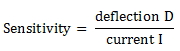
33. Sensitivity is defined as _________
a) amount of voltage per unit current
b) amount of power per unit voltage
c) amount of resistance per unit voltage
d) amount of deflection per unit current

34. Sensitivity is expressed in _________
a) cm/A
b) m/mA
c) mm/µA
d) inch/nA
35. What is the relation between the sensitivity and deflection for a galvanometer?
a) directly proportional
b) inversely proportional
c) independant of each other
d) depends on the type of galvanometer used
36. The voltage sensitivity of a galvanometer is given by _________
a) Sv = e⁄θ
b) Sv = θ⁄e
c) Sv = 1⁄e
d) Sv = 1⁄θ
37. Unit of voltage sensitivity is _________
a) volts per degrees
b) amps per ohms
c) degrees per volts
d) watts per amps
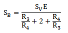
38. Bridge sensitivity is defined as _________
a) 𝑆𝐵=𝜃𝑅
b) 𝑆𝐵=𝜃Δ𝑅
c) 𝑆𝐵=1Δ𝑅𝑅
d) 𝑆𝐵=𝜃Δ𝑅𝑅
39. Maximum sensitivity occurs when?
a) R3 ⁄ R4 = 1
b) R2 ⁄ R4 = 1
c) R1 ⁄ R2 = 1
d) R3 ⁄ R2 = 1
40. What is the significance of the balance equation on losses?
a) independent of losses in inductance
b) independent of losses in capacitance
c) independent of losses in resistance
d) independent of losses in the circuit
41. Balance equation is dependent on frequency.
a) True
b) False
42. How can R1 be scaled?
a) by using a scale
b) by using an ohmmeter
c) by calibration
d) by using a galvanometer
43. Scale of resistance can be calibrated.
a) True
b) False
44. Bridge can be used for the measurement of _________
a) high Q values
b) intermediate Q values
c) very low Q values
d) low Q values
45. The balance condition is _________
a) is easy to obtain
b) is difficult to obtain
c) can’t be obtained
d) exists always
46. Commercial Maxwell bridges measures _________
a) inductances in the range of 1 to 1000H
b) capacitances in the range of 10mF to 1F
c) resistances in the range of 0.001 Ω to 1Ω
d) power in the range of 1W to 50MF
47. At high Q values, the angular balance condition is _________
a) satisfied
b) not satisfied
c) independent of Q factor
d) partially affected
a) True
b) False
49. Schering bridge is used for _________
a) low voltages only
b) low and high voltages
c) high voltages only
d) intermediate voltages only
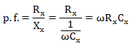
50. Power factor of a Schering bridge is _________
a) p.f. = sin∅x = Zx⁄Rx
b) p.f. = cot∅x = Rx⁄Zx
c) p.f. = cos∅x = Rx⁄Zx
d) p.f. = tan∅x = Rx⁄Zx
51. For phase angles close to 90°, the power factor of the bridge is _________
a) p.f. = ωRx
b) p.f. = ωCx
c) p.f. = Rx Cx
d) p.f. = ωRx Cx
52. For a series RC circuit, what is δ?
a) voltage between series RC combination and C
b) voltage between series RC combination
c) voltage across C
d) voltage across R
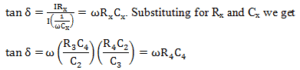
53. What is the expression for the loss angle?
a) tan δ = ωR4
b) tan δ = ωR4 C4
c) tan δ = ωC4
d) tan δ = R4 C4
54. Quality factor is given by which of the following expression?
a) Q = 1⁄R
b) Q = R
c) Q = X⁄R
d) Q = XR
53. Dissipation factor is the reciprocal of quality factor.
a) True
b) False
54. Commercial Schering bridge can be used for the measurement of capacitances from _____________
a) 10pF to 0.1nF
b) 100pF to 1μF
c) 50nF to 10mF
d) 25mF to 5F
55. A Schering bridge can be used for the ______________
a) measuring voltages
b) measuring currents
c) testing capacitors
d) protecting the circuit from temperature rises
1. Resistance temperature detector is ___________
a) a electrical transducer
b) a mechanical transducer
c) a chemical transducer
d) a physical transducer
2. Relation between temperature and resistance of a conductor is ________
a) Rt = Rref [1+t]
b) Rt = Rref [1+α∆t]
c) Rt = Rref [1-αt]
d) Rt = Rref [1-t]
3. Sensing element in the thermometer must provide ________
a) small change in resistance
b) no change in resistance
c) large change in resistance
d) infinite change in resistance
4. Platinum is used for industrial applications because ________
a) it is cheap
b) it is available readily
c) it is a noble metal
d) it gives accurate measurements
5. Resistance thermometer provides the change in electrical resistance.
a) True
b) False
6. If the sensing element is large, then less amount of heat is required.
a) True
b) False
7. Most metallic conductors have a ________
a) neutral temperature coefficient of resistance
b) negative temperature coefficient of resistance
c) positive temperature coefficient of resistance
d) zero temperature coefficient of resistance
8. In a temperature sensing element ________
a) low value of α is required
b) infinite value of α is required
c) α must be zero
d) high value of α is required
9. Nickel and its alloys can be used over a temperature range of ________
a) 100 to 450 K
b) 10 to 50 K
c) 0 to 25 K
d) 5 to 15 K
10. How can corrosion be prevented in a resistance thermometer?
a) by immersing the setup in oil
b) by enclosing the elements in a glass tube
c) by using guard rings
d) by painting the elements
11. Resistance temperature detector is ___________
a) a electrical transducer
b) a mechanical transducer
c) a chemical transducer
d) a physical transducer
Answer: a
Explanation: Resistance temperature detector is an electrical transducer. It is used for measuring the variation in temperature. It is also known as a resistance thermometer.
12. Relation between temperature and resistance of a conductor is ________
a) Rt = Rref [1+t]
b) Rt = Rref [1+α∆t]
c) Rt = Rref [1-αt]
d) Rt = Rref [1-t]
Answer: b
Explanation: The relationship between temperature and resistance of a conductor is given by
Rt = Rref [1+α∆t]
where, Rt is the resistance of the conductor at t°C.
Rref is the resistance of the conductor at reference temperature
α is the temperature coefficient of resistance
∆t is the difference between the temperature being measured and the reference temperature.
13. Sensing element in the thermometer must provide ________
a) small change in resistance
b) no change in resistance
c) large change in resistance
d) infinite change in resistance
Answer: c
Explanation: The sensing element in a thermometer must give a large change in the resistance for a given change in the temperature.
14. Platinum is used for industrial applications because ________
a) it is cheap
b) it is available readily
c) it is a noble metal
d) it gives accurate measurements
Answer: d
Explanation: In industrial applications, platinum is used due to its accuracy in providing measurements. It is also reproducible. Platinum element can be used for the measurement of temperatures of about 1000 K.
15. Resistance thermometer provides the change in electrical resistance.
a) True
b) False
Answer: a
Explanation: A resistance thermometer provides a change in the electrical resistance with respect to a variation in the temperature. Basically resistance thermometers work on the principle of change in the electrical resistance with variation in the temperature.
16. If the sensing element is large, then less amount of heat is required.
a) True
b) False
Answer: b
Explanation: When the sensing element in a resistance thermometer is small in size, then less quantity of heat is required to raise the temperature. Platinum, nickel and copper are the commonly used metals for measuring temperature.
17. Most metallic conductors have a ________
a) neutral temperature coefficient of resistance
b) negative temperature coefficient of resistance
c) positive temperature coefficient of resistance
d) zero temperature coefficient of resistance
Answer: c
Explanation: In general metallic conductors have a positive temperature coefficient of resistance. The resistance increases with an increase in temperature.
18. In a temperature sensing element ________
a) low value of α is required
b) infinite value of α is required
c) α must be zero
d) high value of α is required
Answer: d
Explanation: In order to achieve a large change in the value of resistance for a small change in the value of temperature, high value of α is required. Change in resistance is measured through a Wheatstone’s bridge.
19. Nickel and its alloys can be used over a temperature range of ________
a) 100 to 450 K
b) 10 to 50 K
c) 0 to 25 K
d) 5 to 15 K
Answer: a
Explanation: Temperature sensors constructed using nickel and its alloys can be used in the temperature range of 100 to 450 K. Compared to platinum, they are less expensive. They have a comparatively higher temperature coefficient that increases with temperature.
20. How can corrosion be prevented in a resistance thermometer?
a) by immersing the setup in oil
b) by enclosing the elements in a glass tube
c) by using guard rings
d) by painting the elements
Answer: b
Explanation: Corrosion can be eliminated in a resistance thermometer by enclosing the elements in a protective tubular glass made of pyrex, quartz or crystal depending upon the temperature range.
21. Thermistor is a contraction _________
a) thermal resistor
b) laser resistor
c) electric resistor
d) mechanical resistor
Answer: a
Explanation: Thermistor is basically the short form of a thermal resistor. Resistors which depend on temperature are known as thermal resistors.
22. Thermistors have ________
a) positive temperature coefficient
b) negative temperature coefficient
c) zero temperature coefficient
d) infinite temperature coefficient
Answer: b
Explanation: Thermistor generally has a negative temperature coefficient of resistance. With an increase in temperature, resistance of a thermistor decreases.
23. Thermistors ________
a) sense large changes in temperature
b) cannot sense any change in temperature
c) sense small changes in temperature
d) have a positive temperature coefficient of resistance
Answer: c
Explanation: Thermistors can sense very small changes in temperature. The negative temperature coefficient of thermistors can be a few percent/degree celcius change in temperature.
24. Thermistor has a resistance of ________
a) 250 ῼ to 500 kῼ
b) 50 ῼ to 10 kῼ
c) 1 ῼ to 1 kῼ
d) 100 ῼ to 100 kῼ
Answer: d
Explanation: Thermistor has a resistance range of 100 ῼ to 100 kῼ. Thermistor consists of a mixture of metallic oxides of manganese, nickel, cobalt, copper, iron and uranium.
25. Thermistors are suited for precision temperature measurements.
a) True
b) False
Answer: a
Explanation: Thermistors can be used for precision measurement of temperature, controlling g temperature and for temperature compensation due to a very large variation in resistance with temperature.
26. Change in resistance is measured using a ________
a) Anderson’s bridge
b) Wheatstone’s bridge
c) Hay’s bridge
d) Maxwell’s bridge
Answer: b
Explanation: The change in resistance in a thermistor is measured using a Wheatstone’s bridge. It is used for measurement of resistance in the range of -100°C to +200°C.
27. Thermistor material is pressed ________
a) under zero pressure
b) under low pressure
c) under high pressure
d) under low volume
Answer: c
Explanation: A thermistor material is usually pressed under high pressure to form a flat cylindrical shape. Disks and washers are placed in series or in parallel to increase the power dissipation.
28. Thermistor follows which law for small variations ________
a) Charle’s law
b) KVL
c) KCL
d) Ohm’s law
Answer: d
Explanation: For small changes in the values of current, voltage across a thermistor increases. It attains a peak value. Then the voltage across the thermistor decreases. As a result Ohm’s law is followed at small variations of current.
29. At small values of voltage, a thermistor ________
a) reaches peak current slowly
b) reaches peak current immediately
c) does not reaches peak current
d) reaches peak current intermediately
Answer: a
Explanation: For minute variations in voltage, thermistor reaches peak value of current slowly. As the magnitude of voltage is increased, less time is required to attain peak current.
30. Thermistor has low resistance.
a) True
b) False
Answer: b
Explanation: Thermistor generally has a very high value of resistance. Cables with shield are required to be used for minimising interference.
31. Pressure is the _________
a) force per unit area
b) mass per unit area
c) force per unit volume
d) mass per unit volume
Answer: a
Explanation: Pressure at a point is defined as the force acting per unit area. It is measured at some given point over a surface.
32. Pressure measurement devices make use of ________
a) non-elastic member
b) elastic member
c) bendable member
Answer: b
Explanation: Pressure sensors employ elastic member at the input stage to detect or sense the pressure variations. Elastic members are usually of various forms and convert the pressure into mechanical displacement.
33. Output of electrical transducer is ________
a) inversely proportional to displacement
b) proportional to square of displacement
c) proportional to displacement
d) constant
Answer: c
Explanation: The output of an electrical transducer is proportional to displacement. Displacement is measured using electrical transducers.
34. In general how many pressure sensitive devices are there?
a) 6
b) 20
c) 10
d) 4
Answer: d
Explanation: Usually there are four pressure sensitive devices. They are as follows:
• Diaphragms
• Capsule
• Bourdon tube
• Bellows.
35. Diaphragms in a pressure sensor are of ________
a) 2 types
b) 5 types
c) 10 types
d) 20 types
Answer: a
Explanation: Generally in a pressure sensor we have four pressure sensitive devices. Diaphragm is a type of a pressure sensitive device. They are of two types:
• Flat type
• Corrugated type.
36. Temperature is the only consideration while selecting a diaphragm.
a) True
b) False
Answer: b
Explanation: While selecting a suitable diaphragm for sensing the pressure the following factors are considered important.
• Temperature range
• Shock and vibration
• Frequency response requirements.
37. Capsule type of pressure sensor consists of ________
a) 6 dissimilar diaphragms
b) 4 identical diaphragms
c) 2 identical diaphragms
d) 8 dissimilar diaphragms
Answer: c
Explanation: Capsule is a type of a pressure sensor. It comprises of two identical annular corrugated metal diaphragms that are sealed together to form a shell like enclosure.
38. Bourdon tubes are ________
a) very highly sensitive to shock
b) not sensitive to shock
c) less sensitive to shock
d) more sensitive to shock
Answer: d
Explanation: Bourdon tube is one type of pressure sensor. It is more sensitive to shock and vibrations as compared to diaphragms. Bourdon tube can be used for precision measurements of pressure up to 3 MN/m2.
39. Bellows have 5 to 20 convolutions.
a) True
b) False
Answer: a
Explanation: Bellow is a type of pressure sensor. They have about 5 to 20 convolutions. The number of convolutions depends on the pressure range, displacement, and operating temperature.
40. Sensitivity in a capsule is increased ________
a) through parallel connection of capsules
b) through series connection of capsules
c) through series and parallel connection of capsules
d) by not connecting them at all
Answer: b
Explanation: Capsule is a type of pressure sensor. In a capsule, we can increase the sensitivity by connecting two or more capsules in series. The resultant displacement is equal to the number of capsules.
41.Working of linear variable differential transducer (LVDT) is based on the principle of variable
A. Capacitance
B. Resistance
C. Mutual inductance
D. None of these
Answer: Option C
42.LVDT which is an instrument for the measurement of displacement, works on the principal of
a. Linear inductanceb. Non – linear inductance
c. Mutual inductance
d. Linear capacitance
ANSWER: Mutual inductance
43.Potentiometer is used for the measurement of
a. Linear displacement
b. Angular displacement
c. Non – linear displacement
d. Only (1) and (2)
e. All the above
ANSWER: Only (1) and (2)
44.The displacement measuring instruments is / are
a. Potentiometer
b. LVDT
c. RVDT
d. All of these
ANSWER: All of these
1. In an open loop control system
a) Output is independent of control input
b) Output is dependent on control input
c) Only system parameters have effect on the control output
d) None of the mentioned
Answer: a
Explanation: When the input to a system is independent of the output from the system, then the system is called an open-loop or unmonitored system.
2. For open control system which of the following statements is incorrect ?
a) Less expensive
b) Recalibration is not required for maintaining the required quality of the output
c) Construction is simple and maintenance easy
d) Errors are caused by disturbances
Answer: b
Explanation: Most measuring instruments are open-loop control systems, as for the same input signal, the readings will depend upon things like ambient temperature and pressure.
3. A control system in which the control action is somehow dependent on the output is known as
a) Closed loop system
b) Semiclosed loop system
c) Open system
d) None of the mentioned
Answer: a
Explanation: When output of a system is measured and is continuously compared with the required value, then it is known as closed-loop or monitored system.
4. In closed loop control system, with positive value of feedback gain the overall gain of the system will
a) decrease
b) increase
c) be unaffected
d) none of the mentioned
Answer: a
Explanation: In closed loop control system, the output is measured and through a feedback transducer, it is sent to an error detector which detects any error in the output from the required value thus adjusting the input in a way to get the required output.
5. Which of the following is an open loop control system ?
a) Field controlled D.C. motor
b) Ward leonard control
c) Metadyne
d) Stroboscope
Answer: a
Explanation: In field control D.C. motor, the input is dependent of the output. So it is an open loop control system.
6. Which of the following statements is not necessarily correct for open control system ?
a) Input command is the sole factor responsible for providing the control action
b) Presence of non-linearities causes malfunctioning
c) Less expensive
d) Generally free from problems of non-linearities
Answer: b
Explanation: When the input to a system is independent of the output from the system, then the system is called an open-loop or unmonitored system. It is also called as a calibrated system. Most measuring instruments are open-loop control systems, as for the same input signal, the readings will depend upon things like ambient temperature and pressure.
7. In open loop system
a) the control action depends on the size of the system
b) the control action depends on system variables
c) the control action depends on the input signal
d) the control action is independent of the output
Answer: d
Explanation: When the input to a system is independent of the output from the system, then the system is called an open-loop or unmonitored system.
8. The following has tendency to oscillate.
a) Open loop system
b) Closed loop system
c) Both (a) and (b)
d) Neither (a) nor (b)
Answer: b
Explanation: Both open loop system and closed loop system have the tendency to oscillate.
9. A good control system has all the following features except
a) good stability
b) slow response
c) good accuracy
d) sufficient power handling capacity
Answer: b
Explanation: Repose is not included in a good control system.
10. A car is running at a constant speed of 50 km/h, which of the following is the feedback element for the driver ?
a) Clutch
b) Eyes
c) Needle of the speedometer
d) Steering wheel
Answer: c
Explanation: The needle of the speedometer is only the indicator of the speed and to keep the speed constant, the driver has to maintain the speed of 50 km/h.
11. A signal flow graph is the graphical representation of the relationships between the variables of set linear algebraic equations.
a) True
b) False
Answer: a
Explanation: By definition signal flow graphs are the graphical representation of the relationships between the variables of set linear algebraic equations.
12. A node having only outgoing branches.
a) Input node
b) Output node
c) Incoming node
d) Outgoing node
Answer: a
Explanation: Nodes are the point by which the branches are outgoing or ingoing and this can be input or output node and input node is the node having only outgoing branches.
13. Use mason’s gain formula to find the transfer function of the given signal flow graph:
control-systems-questions-answers-signal-flow-graphs-q3
a) abd/1-(ac)
b) abdeg/1-(bc+ef)+bcef
c) abd/1-(bc+ef)+bcef
d) adcdef/1-(bc+ef)+bcef
Answer: b
Explanation: Using mason’s gain formula transfer function from signal flow graph can be calculated which relates the forward path gain to the various paths and loops.
14. Use mason’s gain formula to find the transfer function of the following signal flow graph:
control-systems-questions-answers-signal-flow-graphs-q4
a) abcd+efg/1-cd-fg-cdfg
b) acdfg+bcefg/1-cd-fg-cdfg
c) abef+bcd/1-cd-fg-cdfg
d) adcdefg/1-cd-fg-cdfg
Answer: b
Explanation: Using mason’s gain formula transfer function from signal flow graph can be calculated which relates the forward path gain to the various paths and loops.
15. Loop which do not possess any common node are said to be ___________ loops.
a) Forward gain
b) Touching loops
c) Non touching loops
d) Feedback gain
Answer: c
Explanation: Loop is the part of the network in which the branch starts from the node and comes back to the same node and non touching loop must not have any node in common.
16. Signal flow graphs:
a) They apply to linear systems
b) The equation obtained may or may not be in the form of cause or effect
c) Arrows are not important in the graph
d) They cannot be converted back to block diagram
Answer: a
Explanation: Signal flow graphs are used to find the transfer function of control system by converting the block diagrams into signal flow graphs or directly but cannot be used for nonlinear systems.
17. Signal flow graphs are reliable to find transfer function than block diagram reduction technique.
a) True
b) False
Answer: a
Explanation: As one set technique and formula is used here but in block diagram technique various methods are involved which increases complexity.
18. The relationship between an input and output variable of a signal flow graph is given by the net gain between the input and output node is known as the overall______________
a) Overall gain of the system
b) Stability
c) Bandwidth
d) Speed
Answer: a
Explanation: The relationship between input and output variable of a signal flow graph is the overall gain of the system.
19. Use mason’s gain formula to calculate the transfer function of given figure:
control-systems-questions-answers-signal-flow-graphs-q9
a) G1/1+G2H
b) G1+G2/1+G1H
c) G2/1+G1H
d) None of the mentioned
Answer: b
Explanation: Use mason’s gain formula to solve the signal flow graph and by using mason’s gain formula transfer function from signal flow graph can be calculated which relates the forward path gain to the various paths and loops.
10. Use mason’s gain formula to find the transfer function of the given figure:
control-systems-questions-answers-signal-flow-graphs-q10
a) G1+G2
b) G1+G1/1-G1H+G2H
c) G1+G2/1+G1H+G2H
d) G1-G2
Answer: c
Explanation: Using mason’s gain formula transfer function from signal flow graph can be calculated which relates the forward path gain to the various paths and loops.
11. In signal flow graph, the product of all ______gains while going through a forward path is known as ‘Path gain’.
a. Branch
b. Path
c. Node
d. Loop
ANSWER: Branch
12 .The value of variables at each node is _________the algebraic sum of all signals arriving at that node.
a. Less than
b. Equal to
c. Greater than
d. None of the above
ANSWER: Equal to
13. Two loops are said to be non-touching only if no common ______exists between them.
a. Loop
b. Feedback path
c. Branch
d. Node
ANSWER: Node
14. For which systems are the signal flow graphs applicable?
a. Causal
b. Invertible
c. Linear time invariant system
d. Dynamic
ANSWER: Linear time invariant system
15. While solving signal flow graph using Mason’s gain equation, what does the second letter in two subscript notation of ‘L’ stand for?
a. Serial number of loop
b. Parallel number of loop
c. Number of touching loops
d. Number of non-touching loops
ANSWER: Number of non-touching loops
16. In a signal flow graph method, how is an overall transfer function of a system obtained?
a. Poisson’s equation
b. Block diagram reduction rules
c. Mason’s equation
d. Lagrange’s equation
ANSWER: Mason’s equation
17. Where are the dummy nodes added in the branch with unity gain?
a. At input & output nodes
b. Between chain nodes
c. Both a and b
d. None of the above
ANSWER: At input & output nodes
18. Which type of node comprises incoming as well as outgoing branches?
a. Source node
b. Sink node
c. Chain node
d. Main node
ANSWER: Chain node
19.According to signal flow graph, which among the following represents the relationship between nodes by drawing a line between them?
a. Branch
b. Self-loop
c. Semi-node
d. Mesh
ANSWER: Branch
20. In a signal flow graph, nodes are represented by small _____
a. Circles
b. Squares
c. Arrows
d. Pointers
ANSWER: Circles
21. Which of the following is not the feature of modern control system?
a) Quick response
b) Accuracy
c) Correct power level
d) No oscillation
Answer: d
Explanation: For a good control system the speed of response and stability must be high and for the slow and sluggish response is not used and undesirable.
22. The output of the feedback control system must be a function of:
a) Reference input
b) Reference output
c) Output and feedback signal
d) Input and feedback signal
View Answer
Answer: d
Explanation: Feedback control system has the property of reducing the error and that is by differencing the output with the desired output and as the equation of the output of the system is C=GR/1+GH.
23. The principle of homogeneity and superposition are applied to:
a) Linear time invariant systems
b) Nonlinear time invariant systems
c) Linear time variant systems
d) Nonlinear time invariant systems
Answer: c
Explanation: Superposition theorem states that for two signals additivity and homogeneity property must be satisfied and that is applicable for the LTI systems.
24. In continuous data systems:
a) Data may be continuous function of time at all points in the system
b) Data is necessarily a continuous function of time at all points in the system
c) Data is continuous at the inputs and output parts of the system but not necessarily during intermediate processing of the data
d) Only the reference signal is continuous function of time
Answer: b
Explanation: Continuous signals are the signals having values for the continuous time and if impulse response decays to zero as time approaches infinity, the system is stable.
25. A linear system at rest is subject to an input signal r(t)=1-e-t. The response of the system for t>0 is given by c(t)=1-e-2t. The transfer function of the system is:
a) (s+2)/(s+1)
b) (s+1)/(s+2)
c) 2(s+1)/(s+2)
d) (s+1)/2(s+2)
Answer: c
Explanation: c(t)=1-e-2t
R(s)=1/s-1/s+1
C(s)=1/s-1/s+2
Tf=2(s+1)/(s+2).
26. In regenerating the feedback, the transfer function is given by
a) C(s)/R(s)=G(s)/1+G(s)H(s)
b) C(s)/R(s)=G(s)H(s)/1-G(s)H(s)
c) C(s)/R(s)=G(s)/1+G(s)H(s)
d) C(s)/R(s)=G(s)/1-G(s)H(s)
Answer: d
Explanation: Regenerating feedback is positive feedback and it increases the infinitely and hence the speed of response of the system reduces.
27. A control system whose step response is -0.5(1+e-2t) is cascaded to another control block whose impulse response is e-t. What is the transfer function of the cascaded combination?
a) 1/(s+2)(s+1)
b) 1/(s+1)s
c) 1/(s+3)
d) 0.5/(s+1)(s+2)
Answer: a
Solution: Laplace transform is the transformation that transforms the time domain into frequency domain and of both the cascaded systems are 1/(s+1)(s+2).
28. A transfer function has two zeroes at infinity. Then the relation between the numerator(N) and the denominator degree(M) of the transfer function is:
a) N=M+2
b) N=M-2
c) N=M+1
d) N=M-1
Answer: b
Explanation: Zeroes at infinity implies two poles at origin hence the type of the system is two and degree of denominator is M=N+2.
29. When deriving the transfer function of a linear element
a) Both initial conditions and loading are taken into account
b) Initial conditions are taken into account but the element is assumed to be not loaded
c) Initial conditions are assumed to be zero but loading is taken into account
d) Initial conditions are assumed to be zero and the element is assumed to be not loaded
Answer: c
Explanation: When deriving the transfer function of a linear element only initial conditions are assumed to be zero, loading cannot be assumed to be zero.
30. If the initial conditions for a system are inherently zero, what does it physically mean?
a) The system is at rest but stores energy
b) The system is working but does not store energy
c) The system is at rest or no energy is stored in any of its part
d) The system is working with zero reference input
Answer: c
Explanation: A system with zero initial condition is said to be at rest since there is no stored energy.
1. A feedback control systems has the inherent capability that its parameter can be adjusted to alter both its transient and steady state responses.
a) True
b) False
Answer: a
Explanation: Feedback’s inherent capability is that its parameter can be adjusted to alter both transient and steady state responses as together they are referred to as time responses.
2. Transient response analysis is done for_________ systems.
a) Unstable
b) Stable
c) Conditionally stable
d) Marginally stable
Answer: b
Explanation: In case the system happens to be unstable, we need not proceed with its transient response analysis.
3. The input signals to control systems are not known fully ahead of time, the characteristics of control system which suddenly strain a control system are:
a) Sudden shock
b) Sudden change
c) Constant velocity and acceleration
d) All of the mentioned
Answer: d
Explanation: System dynamic behavior for analysis and design is therefore judged and compared under standard test signals.
4. Standard test signals in control system are:
a) Impulse signal
b) Ramp signal
c) Unit step signal
d) All of the mentioned
Answer: d
Explanation: Standard test signals are impulse, ramp and unit step all of the above to test the dynamic behavior of the control system.
5. The nature of transient response is revealed by ______________
a) Sine wave
b) Cos wave
c) Tan wave
d) Test signals
Answer: d.
Explanation: The nature is dependent on system poles not on the dynamic inputs.
6. It is generally used to analyze the transient response to one of the standard test signals.
a) True
b) False
Answer: a
Explanation: For analyzing transient response mainly step is used and also other signals mainly ramp and parabolic are not used for this analysis but they are used for steady state analysis.
7. Step signal is the signal whose values is :
a) 1 for all values greater than zero
b) Indeterminate at zero
c) It is zero for time less than zero
d) All of the mentioned
Answer: d
Explanation: Step signal is the signal whose value varies from zero to level in zero time.
8. Ramp input :
a) Denotes constant velocity
b) Value increases linearly with time
c) It denotes constant velocity and varies linearly with time
d) It varies exponentially with time\
Answer: c
Explanation: Ramp signal denotes constant velocity and also basic definition states that its value increases linearly with time.
9. A perfect impulse has one value at zero time instant but otherwise zero elsewhere.
a) True
b) False
Answer: b
Explanation: A perfect impulse signal has infinite value at zero but mathematically only a small pulse is taken with finite limits.
10. To find system’s response by means of convolution integral ____________ of the system is used.
a) Sum
b) Difference
c) Exponential
d) Weighing
Answer: d.
Explanation: Impulse response of a system is the inverse Laplace transfer function of its Laplace function.
11. First order system is defined as :
a) Number of poles at origin
b) Order of the differential equation
c) Total number of poles of equation
d) Total number of poles and order of equation
Answer: d
Explanation: First order system is defined by total number of poles and also which is same as the order of differential equation.
12. A unit step is applied at t=0 to a first order system without time delay. The response has the value of 1.264 units at t=10 mins, and 2 units at steady state. The transfer function of the system is_____________
a) 3/(1+600s)
b) 2/(1+500s)
c) 5/(1+220s)
d) 2/(1+600s)
Answer: d
Explanation: a(t)= k[1-e^-t/T] K=2
0.632= 1-e^-10/T
T=600 sec
G(s)=2/(1+600s).
13. The transfer function of the system is G(s) =100/(s+1) (s+100). For a unit step input to the system the approximate settling time for 2% criterion is:
a) 100 sec
b) 4 sec
c) 1 sec
d) 0.01 sec
Answer: b
Explanation: G(s) =100/(s+1) (s+100)
Taking the dominant pole consideration,
S=-100 pole is not taken.
G(s)= 100/s+1
Now it is first order system, ts=4T=4 sec.
15. The unit impulse response of a system having transfer function K/(s+a) is shown below. The value of a is :
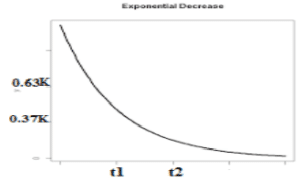
a) t1
b) t2
c) 1/t1
d) 1/t2
Answer: d
Explanation: G(s) = K/s+a
C(s) =K/(s+a) Since R(s) =1
C(t) =Ke^-at
T=1/a
C(t) =0.37K
T= t2=1/a.
16. A system with transfer function 1/Ts+1, subjected to a step input takes to seconds to reach 50% of step height. The value of t is :
a) 6.9s
b) 10s
c) 14.4s
d) 20s
Answer: c
Explanation: The response of a first order system is:
A(t)=a[1-e^-t/T] ½= 1-e^-10/t
T= 14.43 sec.
17.A first order system and its response to a unit step input are shown in figure below. The system parameters are____________
a) a=5 and k=12
b) a=10 and k=5
c) a=5 and k=10
d) a=8 and k=9
Answer: c
Explanation: time constant=0.2 sec.
1/a=0.2
a=5
final value=lims→0 sC(s) =K/a
K/a=2
K=10.
18. Assertion (A): It is observed that step function is first derivative of a ramp function and impulse function is first derivative of a step function.
Reason (R): From the derived time response expression it is concluded that the output time response also follows the same sequence as that of input functions.
a) Both A and R are true and R is the correct explanation of A
b) Both A and R are true but R is not correct explanation of A
c) Both A is True but R is false
d) Both A is False but R is true
Answer: b
Explanation: If response due to one standard signal is known then response due to other signals can also be derived.
19. Laplace transform of unit impulse signal is :
a) A/s
b) A
c) 1
d) 1/s
Answer: c
Explanation: Laplace response of impulse signal is one which implies Laplace response is systems response.
20. Time response during steady state the output velocity matches with the input velocity but lags behind the input by T.
a) True
b) False
Answer: a
Explanation: In first order systems the time response during steady state the output velocity matches
21. What will be the nature of time response if the roots of the characteristic equation are located on the s-plane imaginary axis?
a) Oscillations
b) Damped oscillations
c) No oscillations
d) Under damped oscilaations
Answer: c
Explanation: complex conjugate (non-multiple): oscillatory (sustained oscillations)
Complex conjugate (multiple): unstable (growing oscillations).
22. Consider a system with transfer function G(s) = s+6/Ks2+s+6. Its damping ratio will be 0.5 when the values of k is:
a) 2/6
b) 3
c) 1/6
d) 6
Answer: c
Explanation: s+6/K[s2+s/K+6/K] Comparing with s2+2Gw+w2
w= √6/K
2Gw=1/K
2*0.5*√6/K =1/K
K=1/6.
23. The output in response to a unit step input for a particular continuous control system is c(t)= 1-e-t. What is the delay time Td?
a) 0.36
b) 0.18
c) 0.693
d) 0.289
Answer: c
Explanation: The output is given as a function of time. The final value of the output is limn->∞c(t)=1; . Hence Td (at 50% of the final value) is the solution of 0.5=1-e-Td, and is equal to ln 2 or 0.693 sec.
24. Which one of the following is the most likely reason for large overshoot in a control system?
a) High gain in a system
b) Presence of dead time delay in a system
c) High positive correcting torque
d) High retarding torque
Answer: c
Explanation: Large overshoot refers to the maximum peak in the response of the closed loop system and this is mainly due to the high positive correcting torque.
25. For the system 2/s+1, the approximate time taken for a step response to reach 98% of its final value is:
a) 1s
b) 2s
c) 4s
d) 8s
Answer: c
Explanation: C(s)/R(s) = 2/s+1
R(s) = 1/s (step input)
C(s) = 2/s(s+1)
c(t) = 2[1-e-t] 1.96 = 2[1-e-T] T= 4sec.
26. The unit step response of a second order system is = 1-e-5t-5te-5t . Consider the following statements:
1. The under damped natural frequency is 5 rad/s.
2. The damping ratio is 1.
3. The impulse response is 25te-5t.
Which of the statements given above are correct?
a) Only 1 and 2
b) Only 2 and 3
c) Only 1 and 3
d) 1,2 and 3
Answer: d
Explanation: C(s) = 1/s-1/s+5-5/(s+5)^2
C(s) = 25/s(s2+10s+25)
R(s) = 1/s
G(s) = 25/(s2+10s+25 )
w= √25
w = 5 rad/sec
G = 1.
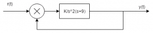
27. The loop transfer function of controller Gc(s) is :
a) 1+0.1s/s
b) -1+0.1s/s
c) –s/s+1
d) s/s+1
Answer: a
Explanation: The transfer function of the controller is 0.1s+1/s
Gc(s) = 0.1s+1/s.
28. The peak percentage overshoot of the closed loop system is :
a) 5.0%
b) 10.0%
c) 16.3%
d) 1.63%
Answer: c
Explanation: C(s)/R(s) = 1/s2+s+1
C(s)/R(s) = w/ws2+2Gws+w2
Compare both the equations,
w = 1 rad/sec
2Gw = 1
Mp = 16.3 %
29. Consider a second order all-pole transfer function model, if the desired settling time(5%) is 0.60 sec and the desired damping ratio 0.707, where should the poles be located in s-plane?
a) -5+j4√2
b) -5+j5
c) -4+j5√2
d) -4+j7
Answer: b
Explanation: G = 1/√2
Gw = 5
s = -5+j5.
30. Which of the following quantities give a measure of the transient characteristics of a control system, when subjected to unit step excitation.
1. Maximum overshoot
2. Maximum undershoot
3. Overall gain
4. Delay time
5. Rise time
6. Fall time
a) 1,3 and 5
b) 2, 4 and 5
c) 2,4 and 6
d) 1,4 and 5
Answer: d
Explanation: Maximum overshoot, rise time and delay time are the major factor of the transient behaviour of the system and determines the transient characteristics.
31. Which of the following transfer function will have the greatest maximum overshoot?
a) 9/(s2+2s+9)
b) 16/(s2+2s+16)
c) 25/(s2+2s+25)
d) 36/(s2+2s+36)
Answer: d
Explanation: Comparing the characteristic equation with the standard equation the value of the damping factor is calculated and the value for the option d is minimum hence the system will have the maximum overshoot .
32. A system generated by ![]() The ramp component in the forced response will be:
The ramp component in the forced response will be:
a) t u(t)
b) 2t u(t)
c) 3t u(t)
d) 4t u(t)
Answer: b
Explanation: ![]()
Laplace transforming
sY(s) + 2Y(s)=4/s2
Taking the inverse Laplace transform the forced term is 2t u(t).
33. The system in originally critically damped if the gain is doubled the system will be :
a) Remains same
b) Overdamped
c) Under damped
d) Undamped
Answer: c
Explanation: ![]() hence due to this G lies between 0 and 1.
hence due to this G lies between 0 and 1.
34. Let c(t) be the unit step response of a system with transfer function K(s+a)/(s+K). If c(0+) = 2 and c(∞) = 10, then the values of a and K are respectively.
a) 2 and 10
b) -2 and 10
c) 10 and 2
d) 2 and -10
Answer: c
Explanation: Applying initial value theorem which state that the initial value of the system is at time t =0 and this is used to find the value of K and final value theorem to find the value of a.
35. The damping ratio and peak overshoot are measures of:
a) Relative stability
b) Speed of response
c) Steady state error
d) Absolute stability
Answer: b
Explanation: Speed of response is the speed at which the response takes the final value and this is determined by damping factor which reduces the oscillations and peak overshoot as the peak is less then the speed of response will be more.
36. Find the type and order of the system given below:
a) 2,3
b) 2,2
c) 3,3
d) None of the mentioned
Answer: Type = 2 which is the number of poles at the origin and order is the highest power of the characteristic equation.
37. A system has a complex conjugate root pair of multiplicity two or more in its characteristic equation. The impulse response of the system will be:
a) A sinusoidal oscillation which decays exponentially; the system is therefore stable
b) A sinusoidal oscillation with a time multiplier ; the system is therefore unstable
c) A sinusoidal oscillation which rises exponentially ; the system is therefore unstable
d) A dc term harmonic oscillation the system therefore becomes limiting stable
Answer: c
Explanation: Poles are the roots of the denominator of the transfer function and on imaginary axis makes the system stable but multiple poles makes the system unstable.
38. The forward path transfer function is given by G(s) = 2/s(s+3). Obtain an expression for unit step response of the system.
a) 1+2e-t+e-2t
b) 1+e-t-2e-2t
c) 1-e-t+2e-2t
d) 1-2e-t+e+2t
Answer: d
Explanation: C(s)/R(s) = s/(s2+3s+2)
C(s) = 1/s-2/s+1+1/s+2
c(t) = 1-2e-t+e+2t.
39. Find the initial and final values of the following function:
F(s) = 12(s+1)/s(s+2)^2(s+3)
a) 1,∞
b) 0,∞
c) ∞,1
d) 0,1
Answer: d
Explanation: Using final and initial values theorem directly to find initial and final values but keeping in mind that final value theorem is applicable for stable systems only.
40. The step response of the system is c(t) = 10+8e-t-4/8e-2t . The gain in time constant form of transfer function will be:
a) -7
b) 7
c) 7.5
d) -7.5
Answer: d
Explanation: Differentiating the equation and getting the impulse response and then taking the inverse Laplace transform and converting the form into time constant form we get K = -7.5.
41. The standard second order system to a unit step input shows the 0.36 as the first peak undershoot, hence its second overshoot is:
a) 0.135
b) 0.216
c) 0.1296
d) 0.116
Answer: b
Explanation: Overshoot and undershoot are calculated from the formula of peak time as odd peaks denote the overshoot and even denotes the under shoot.
42. Consider the input with the inputs 4 u(t) and the impulse response 5 +7 , the time constants of the output are,
a) 0.2, 0.33 and 0.5
b) 4.5 and 7
c) 0.2, 0.4 and 0.7
d) 0.2, 0.1 and 0.25
Answer: a
Explanation: Output response so calculated is the inverse Laplace transform of the input and impulse response and hence converting the resultant form in the time constant form time constant can be directly determined.
43. In a second order feedback control system natural frequency and damping
a) Can be designed by changing the gain of the individual system
b) Cannot be designed by changing the gain of the individual system
c) Are independent on the type of input excitation
d) None of the mentioned
Answer: a
Explanation: Natural frequency and damping can be designed by changing the gain of the individual system.
44. Undamped natural frequency of a second order system has the following influence on the response due to various excitations:
a) Increase in speed of response and decrease sensitivity
b) Decrease in speed of response and increase sensitivity
c) Has no influence in the dynamic response
d) Increase oscillatory behavior
Answer: a
Explanation: Undamped natural frequency is the frequency that has suffered damping and gets affected by the increase in the speed of response and decrease in sensitivity.
45. Normalized response of a dynamic system refers to:
a) Characteristic feature of a response due to specific excitation irrespective of its amplitude
b) Response of dynamic system divided by its maximum value
c) Response of dynamic system divided by a standard value
d) None of the mentioned
Answer: a
Explanation: Normalization refers to the desired to the reference value and normalized response of the dynamic system refers to the characteristic feature of a response due to specific excitation irrespective of its amplitude.
46. The transfer function of a system is G(s) = 100/(s+1) (s+100). For a unit step input to the system the approximate settling time for 2% criterion is:
a) 100 sec
b) 4 sec
c) 1 sec
d) 0.01 sec
Answer: b
Explanation: Comparing the equation with the characteristic equation and then finding the value of G and w and calculating the value of settling time as 4 sec from 4/Gw.
47. The characteristic equation of a control system is s(s2+ 6s+13)+K=0. The value of k such that the characteristic equation has a pair of complex roots with real part -1 will be :
a) 10
b) 20
c) 30
d) 40
Answer: b
Explanation: The characteristic equation is considered and the values of G and w are calculated and further the value of k can be calculated.
48. Normalized difference between the time response peak and steady state output is ______________
a) Maximum peak overshoot
b) Damping factor
c) Minimum peak overshoot
d) Undershoot
Answer: a
Explanation: Maximum peak overshoot is the normalized difference between the time response peak and steady state output.
49. Rise time, Peak time, maximum peak overshoot, settling time, and steady state error are mutually dependent.
a) True
b) False
Answer: a
Explanation: Rise time, peak time, settling time and maximum peak overshoot are the prime factors of the time domain analysis and they must be specified in a consistent manner but they are mutually dependent.
50. Control system are normally designed to be:
a) Overdamped
b) Under damped
c) Un damped
d) Critically damped
Answer: b
Explanation: Practically there are some non-linearity present in the system as friction but in mathematical model these are considered by considering high gain and lower damping.
51. The steady state error for a unity feedback system for the input r(t) to the system G(s) = K(s+2)/s(s3+7s2+12s) is 6R/K. The input r (t) is _______
a) Rt2/2
b) Rt3/2
c) Rt5/2
d) Rt7/2
Answer: a
Explanation: Ka = 2K/12 = K/6. Ess = 6R/K. So, as we take Rt2/2 we get 6R/K as the error. The other options can’t be true because the input is exceeding the desired input. It is inversely proportional to the gain.
52. The ramp input is applied to a unity feedback system with type number 1 and zero frequency 20. What is the percentage of steady state error?
a) 1%
b) 2%
c) 5%
d) 9%
Answer: c
Explanation: Steady state error is the error calculated between the final output and desired output and the error must be less and this steady state error is inversely proportional to gain. Here unity feedback system is given with zero frequency 20 so we take 1/20th part and the answer comes as 5%.
53. A unit integrator is applied to a modified system along with a ramp input. The modified value of the steady state error is 0.25. What was the initial value?
a) 0.05
b) 0.1
c) 0.15
d) 0.2
Answer: d
Explanation: The integrator is similar to the phase lag systems and it is used to reduce or eliminate the steady state error and when it is cascaded with the ramp input. We know that when unit integrator is applied with a ramp input the steady state error will automatically increase but here we wanted the initial value which will be obviously less than the modified steady state error and by the same proportion.
54. Systems of type higher than 1 are not employed in practice.
a) True
b) False
Answer: b
Explanation: Systems of type higher than 2 are not employed in practice as they’re difficult to stabilize and dynamic error increases. Systems of type 2 or lower are already stable and has less dynamic error.
55. The initial response when output is not equal to input is ______
a) Error response
b) Transient response
c) Dynamic response
d) Static response
Answer: b
Explanation: The response is not long last lasting and real, so it is a transient response. It can’t be a static or dynamic response as the output doesn’t match the input and also there’s no chance of error response.
56. The steady state error for a unit step input is ________
a) 1/kp
b) 1/(1-kp)
c) 1/2kp
d) 1/(1+kp)
Answer: d
Explanation: R(s) =1/s for unit step and for the transfer function whose limit tends to zero, it is 1/1+kp. We use Laplace and Inverse Laplace Transform to calculate the same.
57. For a unity feedback system, the open loop transfer function is G(s) = K(s+2)/s2 (s2+7s+12). What is the type of system?
a) One
b) Two
c) Three
d) Four
Answer: b
Explanation: As in the numerator it is mentioned K(s+2) so we got two poles in the open loop transfer function at the origin. For a given transfer function we calculate poles and zeros and the number of poles determine the type of the system.
58. The For a unity feedback system the open loop transfer function is G(s) = K(s+2)/s2 (s2+7s+12). What is the value of Ka?
a) 12/k
b) k/12
c) k/6
d) 6/k
Answer: c
Explanation: As limit s tends to zero : s2G(s) = K(s+2)/ (s2+7s+12) = k/6. Ka is the acceleration error constant which is calculated by the above method.
59. For a system whose transfer function is G(s) =10/s (1+s), what are the dynamic error coefficients k2 & k3 respectively as k1 is infinity?
a) 11, 10.1
b) 10.1, 11
c) 10, 11.1
d) 9, 10.1
Answer: c
Explanation: We should compare it with E(s)/R(s) = 1/k1+1/k2s+1/k3s2. G(s) = 10/s(1+s) is compared with the above equation which is the parent equation for calculating dynamic error constants where k1 comes as infinity and K2, K3 takes the value of 10 & 11.1 respectively.
60. The Laplace transform of a parabolic signal is _______
a) 1
b) A/s3
c) A/s2
d) A/s
Answer: a
Explanation: As u(t) is a unity step function r(t)=0;t<0 and r(t)=1; t=0. The parabolic signal is a signal which has varying amplitudes and when we take Laplace Transform of that we get 1 as the answer.
61. Which of the following is not the correct reason to select feedback compensation over cascaded one?
a) No amplification is required as the energy transfer is from higher to lower level.
b) Suitable devices are not available for compensation(series)
c) It is economical
d) Provides greater stiffness against load disturbances
Answer: c
Explanation: Feedback compensation is the compensation obtained due to feedback and cascade refers to the cascading of blocks in the forward path and feedback compensation is not preferred over cascading as it is ecenomical.
62. Operations performed by pneumatic controllers:
a) Flexible operations
b) High torque high speed operations
c) Fire and explosion proof operation
d) All of the mentioned
Answer: c
Explanation: Pneumatic controllers are the controllers that perform the control action to control the motion related to air and they always perform fire and explosion proof operation.
63. Operations performed by hydraulic controllers:
a) Flexible operations
b) High torque high speed operations
c) Fire and explosion proof operation
d) All of the mentioned
Answer: b
Explanation: Hydraulic controllers are the controllers that perform the control action in which the motion is due to the water and they have high torque and high speed operations.
64. Operations performed by electronic controllers:
a) Flexible operations
b) High torque high speed operations
c) Fire and explosion proof operation
d) All of the mentioned
Answer: a
Explanation: Electronic controllers are the most flexible controller and used over hydraulic and pneumatic controllers and they use the control action where the control is mainly handled by electronic components and can perform flexible operations as of high speed and high torque.
65. The compensator G(s) =5(1+0.3s)/1+0.1s would provide a maximum phase shift of:
a) 20°
b) 30°
c) 45°
d) 60°
Answer: b
Explanation: The two corner frequencies are 1/0.3 and 1/0.1. The maximum phase lead occurs at mid frequency w =10/√ and maximum phase is 30°.
66. Consider the following systems:
System 1: G(s) =1/ (2s+1) and System 2: G(s) =1/ (5s+1)
The true statement regarding the system is:
a) Bandwidth of the system 1 is greater than the bandwidth of the system 2
b) Bandwidth of the system 1 is lower than the bandwidth of the system 2
c) Bandwidth of both the systems are same
d) Bandwidth of both the systems are infinite
Answer: a
Explanation: For the system 1 B.W. is 0.5 and
For the system 2 B.W. is 0.2
Hence the system 1 is having more bandwidth compared to system 2.
67. With regard to the filtering capacity the lead compensator and lag compensator are respectively:
a) Low pass and high pass filter
b) High pass and low pass filter
c) Both high pass filter
d) Both low pass filters
Answer: b
Explanation: Lead compensator is similar to high pass filter which allows only the high frequencies to pass and rejects all the other and Lag compensator is similar to Low pass filter which allows only low frequencies to pass and rejects other.
68. What is the effect of phase lag compensation on the performance of a servo system?
a) For a given relative stability, the velocity constant is increased
b) For a given relative stability, the velocity constant is decreased
c) The bandwidth of the system is increased
d) The time response is made faster
Answer: a
Explanation: Phase lag compensation is an integrator. It reduces the steady state error.
Velocity constant =1/steady state error
So velocity constant is increased.
69. A composite R-C network yielded the following transfer function when calculated from its components:
T(s) = 1+21s+20s2/1+11s+10s2. This network can be used as which one of the following?
a) Phase lead compensator
b) Phase lag compensator
c) Lag lead compensator
d) None of the mentioned
Answer: a
Explanation: T(s) = 1+20s/1+10s.
Since zero is nearer to origin than pole, it is a phase lead compensator.
70. The open loop transfer function of a plant is given as, G(s) =1/s^2-1. If the plant is operated in unity feedback configuration, then the lead compensator that can stabilize the control system is:
a) 10(s-1)/(s+2)
b) 10(s+4)/(s+2)
c) 10(s+2)/(s+10)
d) 10(s+2)/(s+10)
Answer: a
Explanation: G(s) =1/(s-1)(s+1)
The lead compensator C(s) should stabilize the plant as it is similar to the differentiator and the tendency of it is to stablize the system by increasing the damping hence remove the first term so only option (a) satisfies.
1. Stability of a system implies that :
a) Small changes in the system input does not result in large change in system output
b) Small changes in the system parameters does not result in large change in system output
c) Small changes in the initial conditions does not result in large change in system output
d) All of the above mentioned
Answer: d
Explanation: Stability of the system implies that small changes in the system input, initial conditions, and system parameters does not result in large change in system output.
2. A linear time invariant system is stable if :
a) System in excited by the bounded input, the output is also bounded
b) In the absence of input output tends zero
c) Both a and b
d) System in excited by the bounded input, the output is not bounded
Answer: c
Explanation: A system is stable only if it is BIBO stable and asymptotic stable.
3. Asymptotic stability is concerned with:
a) A system under influence of input
b) A system not under influence of input
c) A system under influence of output
d) A system not under influence of output
Answer: b
Explanation: Asymptotic stability concerns a free system relative to its transient behavior.
4. Bounded input and Bounded output stability notion concerns with :
a) A system under influence of input
b) A system not under influence of input
c) A system under influence of output
d) A system not under influence of output
Answer: a
Explanation: BIBO stability concerns with the system that has input present.
5. If a system is given unbounded input then the system is:
a) Stable
b) Unstable
c) Not defined
d) Linear
Answer: c
Explanation: If the system is given with the unbounded input then nothing can be clarified for the stability of the system.
6. Linear mathematical model applies to :
a) Linear systems
b) Stable systems
c) Unstable systems
d) Non-linear systems
Answer: b
Explanation: As the output exceeds certain magnitude then the linear mathematical model no longer applies.
7. For non-linear systems stability cannot be determined due to:
a) Possible existence of multiple equilibrium states
b) No correspondence between bounded input and bounded output stability and asymptotic stability
c) Output may be bounded for the particular bounded input but may not be bounded for the bounded inputs
d) All of the mentioned
Answer: d
Explanation: For non-linear systems stability cannot be determined as asymptotic stability and BIBO stability concepts cannot be applied, existence of multiple states and unbounded output for many bounded inputs.
8. If the impulse response in absolutely integrable then the system is :
a) Absolutely stable
b) Unstable
c) Linear
d) Stable
Answer: a
Explanation: The impulse response must be absolutely integrable for the system to absolutely stable.
9. The roots of the transfer function do not have any effect on the stability of the system.
a) True
b) False
Answer: b
Explanation: The roots of transfer function also determine the stability of system as they may be real, complex and may have multiplicity of various order.
10. Roots with higher multiplicity on the imaginary axis makes the system :
a) Absolutely stable
b) Unstable
c) Linear
d) Stable
Answer: b
Explanation: Repetitive roots on the imaginary axis makes the system unstable.
11. Roots on the imaginary axis makes the system :
a) Stable
b) Unstable
c) Marginally stable
d) Linear
Answer: c
Explanation: Roots on the imaginary axis makes the system marginally stable.
12. If the roots of the have negative real parts then the response is ____________
a) Stable
b) Unstable
c) Marginally stable
d) Bounded
Answer: d
Explanation: If the roots of the have negative real parts then the response is bounded and eventually decreases to zero.
13. If root of the characteristic equation has positive real part the system is :
a) Stable
b) Unstable
c) Marginally stable
d) Linear
Answer: b
Explanation: The impulse response of the system is infinite when the roots of the characteristic equation has positive real part.
14. A linear system can be classified as :
a) Absolutely stable
b) Conditionally stable
c) Unstable
d) All of the mentioned
Answer: d
Explanation: A system can be stable, unstable and conditionally stable also.
15. ___________ is a quantitative measure of how fast the transients die out in the system.
a) Absolutely stable
b) Conditionally stable
c) Unstable
d) Relative Stability
Answer: d
Explanation: Relative Stability may be measured by relative settling times of each root or pair of roots.
16. Routh Hurwitz criterion gives:
a) Number of roots in the right half of the s-plane
b) Value of the roots
c) Number of roots in the left half of the s-plane
d) Number of roots in the top half of the s-plane
Answer: a
Explanation: Routh Hurwitz criterion gives number of roots in the right half of the s-plane.
17. Routh Hurwitz criterion cannot be applied when the characteristic equation of the system containing coefficient’s which is/are
a) Exponential function of s
b) Sinusoidal function of s
c) Complex
d) Exponential and sinusoidal function of s and complex
Answer: d
Explanation: Routh Hurwitz criterion cannot be applied when the characteristic equation of the system containing coefficient/s which is/are exponential, sinusoidal and complex function of s.
18. Consider the following statement regarding Routh Hurwitz criterion:
a) It gives absolute stability
b) It gives gain and phase margin
c) It gives the number of roots lying in RHS of the s-plane
d) It gives gain, phase margin and number of roots lying in RHS of the s-plane
Answer: d
Explanation: Routh Hurwitz gives the absolute stability and roots on the right of the s plane.
19. The order of the auxiliary polynomial is always:
a) Even
b) Odd
c) May be even or odd
d) None of the mentioned
Answer: a
Explanation: Auxiliary polynomial denotes the derivative of the odd equation which is always even.
20. Which of the test signals are best utilized by the stability analysis.
a) Impulse
b) Step
c) Ramp
d) Parabolic
Answer: a
Explanation: Computational task is reduced to much extent.
21. The characteristic equation of a system is given as3s4+10s3+5s2+2=0. This system is :
a) Stable
b) Marginally stable
c) Unstable
d) Linear
Answer: c
Explanation: There is a missing coefficient so the system is unstable.
22. The characteristic equation of a system is given ass3+25s2+10s+50=0. What is the number of the roots in the right half s-plane and the imaginary axis respectively?
a) 1,1
b) 0,0
c) 2,1
d) 1,2
Answer: b
Explanation: The characteristic equation has no sign changes so number of roots on the right half of s plane is zero.
23. Consider the following statement:
a) A system is said to be stable if its output is bounded for any input
b) A system is said to be stable if all the roots of the characteristic equation lie on the left half of the s plane.
c) A system is said to be stable if all the roots of the characteristic equation have negative real parts.
d) A second order system is always stable for finite values of open loop gain
Answer: a
Explanation: A system is stable if its output is bounded for bounded input.
24. The necessary condition for the stability of the linear system is that all the coefficients of characteristic equation 1+G(s)H(s) =0, be real and have the :
a) Positive sign
b) Negative sign
c) Same sign
d) Both positive and negative
Answer: c
Explanation: The necessary condition for the stability of the linear system is that all the coefficients of characteristic equation 1+G(s)H(s) =0, is they must have same sign.
25. For making an unstable system stable:
a) Gain of the system should be increased
b) Gain of the system should be decreased
c) The number of zeroes to the loop transfer function should be increased
d) The number of poles to the loop transfer function should be increased
Answer: b
Explanation: For making an unstable system stable gain of the system should be decreased.
26. A system with unity feedback having open loop transfer function as G(s) = K(s+1)/s3+as2+2s+1. What values of ‘K’ and ’a’ should be chosen so that the system oscillates ?
a) K =2, a =1
b) K =2, a =0.75
c) K =4, a =1
d) K =4, a =0.75
Answer: b
Explanation: Solving Routh Hurwitz table whenever row of zero occurs, the roots are located symmetrically on the imaginary axis then the system response oscillates, a =1+K/2+K. If K =2 is consider then a =0.75.
27. The open loop transfer functions with unity feedback are given below for different systems.
Among these systems the unstable system is
a) G(s) =2/s+2
b) G(s) =2/s(s+2)
c) G(s) =2/(s+2)s^2
d) G(s) =2(s+1)/s(s+2)
Answer: c
Explanation: 1+2/s^2(s+2) =0. The coefficient of‘s’ is missing. Hence the system is unstable.
28. Determine the stability of closed loop control system whose characteristic equation is
s5+s4+2s3+2s2+11s+10=0.
a) Stable
b) Marginally stable
c) Unstable
d) None of the mentioned
View Answer
Answer: b
Explanation: By Routh array s =0 and s =+j. It is having a pair of conjugate root lying on imaginary axis. System is marginally stable.
29. Determine the condition for the stability of unity feedback control system whose open loop transfer function is given by
G(s) = 2e-st/s(s+2)
a) T >1
b) T <0
c) T <1
d) T >0
Answer: c
Explanation: G(s) =2(1-sT)/s(s+2)
By Routh array analysis, for stable system, all the elements of first column need to be positive T<1.
30.Determine the value of K such that roots of characteristic equation given below lies to the left of the line s = -1. s3+10s2+18s+K.
a) K>16 and K<9
b) K<16
c) 9<K<16
d) K<9
Answer: c
Explanation: In Routh array analysis the first column must be positive and after solving K<16 and K>9.
31. Consider a negative feedback system where G(s) =1/(s+1) and H(s) =K/s(s+2). The closed loop system is stable for
a) K>6
b) 0<K<2
c) 8<K<14
d) 0<K<6
Answer: d
Explanation: Using Routh array, for stability k<6.
32. The characteristic equation of a feedback control system is s3+Ks2+9s+18. When the system is marginally stable, the frequency of the sustained oscillation:
a) 1
b) 1.414
c) 1.732
d) 3
Answer: d
Explanation: Solve using Routh array and for the system to be marginally stable, K = -2. Polynomial for sustained oscillation w = 3 rad/s.
33. Consider a characteristic equation, s4+3s3+5s2+6s+k+10=0. The condition for stability is
a) K>5
b) -10<K
c) K>-4
d) -10<K<-4
Answer: d
Explanation: Solve Roth array for the system stable, -10<K<4.
34. The polynomial s4+Ks3+s2+s+1=0 the range of K for stability is _____________
a) K>5
b) -10<K
c) K>-4
d) K-1>0
Answer: d
Explanation: Solving using Routh array we get K-1>0 and is always negative for K>1.
35. The characteristic equation of a system is given by3s4+10s3+5s2+2=0. This system is:
a) Stable
b) Marginally stable
c) Unstable
d) Linear
Answer: c
Explanation: There is missing coefficient so system is unstable.
36. Which one of the following statements is not correct?
a) Root loci can be used for analyzing stability and transient performance
b) Root loci provide insight into system stability and performance
c) Shape of the root locus gives idea of type of controller needed to meet design specification
d) Root locus can be used to handle more than one variable at a time
Answer: d
Explanation: For more than one variable state space is used.
37. Root locus of s(s+2)+K(s+4) =0 is a circle. What are the coordinates of the center of this circle?
a) -2,0
b) -3,0
c) -4,0
d) -5,0
Answer: c
Explanation: s(s+2)+K(s+4) =0
1+K(s+4)/s(s+2) =0.
G(s)H(s) =K(s+b)/s(s+a)
Centre =(-b,0) =(-4,0).
38. The main objective of drawing root locus plot is :
a) To obtain a clear picture about the open loop poles and zeroes of the system
b) To obtain a clear picture about the transient response of feedback system for various values of open loop gain K
c) To determine sufficient condition for the value of ‘K’ that will make the feedback system unstable
d) Both b and c
Answer: d
Explanation: The main objective of drawing root locus plot is to obtain a clear picture about the transient response of feedback system for various values of open loop gain K and to determine sufficient condition for the value of ‘K’ that will make the feedback system unstable.
39. While increasing the value of gain K, the system becomes
a) Less stable
b) More stable
c) Unstable
d) Absolute stable
Answer: a
Explanation: Damping factor is inversely proportional to gain on increasing gain it reduces hence makes the system less stable.
40. The addition of open loop poles pulls the root locus towards:
a) The right and system becomes unstable
b) Imaginary axis and system becomes marginally stable
c) The left and system becomes unstable
d) The right and system becomes unstable
Answer: d
Explanation: The addition of open loop poles pulls the root locus towards the right and system becomes unstable.
41. Root locus is used to calculate:
a) Marginal stability
b) Absolute stability
c) Conditional stability
d) Relative stability
Answer: d
Explanation: Root locus is used to calculate relative stability.
42. Routh Hurwitz criterion is better than root locus.
a) True
b) False
Answer: b
Explanation: Root locus is better as it require less computation process.
43. Consider the following statements regarding root loci:
a) All root loci start from the respective poles of G(s) H(s)
b) All root loci end at the respective zeros of G(s) H(s) or go to infinity
c) The root loci are symmetrical about the imaginary axis of the s-plane
d) All root loci start and end from the respective poles of G(s) H(s) or go to infinity
Answer: b
Explanation: All the root locus start at respective poles and end at zeroes.
44. Number of roots of characteristic equation is equal to the number of ______________
a) Branches
b) Root
c) Stem
d) Poles
Answer: a
Explanation: Number of roots of characteristic equation is equal to the number of branches.
45. Which of the following statements are correct?
a) Root locus is for the negative feedback systems
b) Complementary root locus is for the positive feedback systems
c) Root locus is for the negative feedback and Complementary root locus is for the positive feedback systems
d) Complementary root locus is for the negative feedback systems
Answer: c
Explanation: Root locus and Complementary root locus are complementary to each other.
46. Consider the loop transfer function K(s+6)/(s+3)(s+5) In the root locus diagram the centroid will be located at:
a) -4
b) -1
c) -2
d) -3
Answer: c
Explanation: Centroid =Sum of real part of open loop pole-sum of real part of open loop zeros/P-Z.
47. Which one of the following applications software’s is used to obtain an accurate root locus for?
a) LISP
b) MATLAB
c) dBase
d) Oracle
Answer: b
Explanation: MATLAB stands for mathematics laboratory in which the input is in the form of the matrix and is the best software for drawing root locus.
48. Which one of the following is not the property of root loci?
a) The root locus is symmetrical about imaginary axis
b) They start from the open loop poles and terminate at the open loop zeroes
c) The breakaway points are determined from dK/ds = 0
d) Segments of the real axis are the part of the root locus if and only is the total number of real poles and zeroes to their right is odd.
Answer: a
Explanation: The root locus is the locus traced due to the gain of the system with changing frequency and need not be symmetrical about origin.
49. The breakaway point calculated mathematically must always lie on the root locus.
a) True
b) False
Answer: a
Explanation: The breakaway point of the two branches of the root locus is the point where the two branches either meet or they break and may or may not always lie on the root locus.
50. What is the number of the root locus segments which do not terminate on zeroes?
a) The number of poles
b) The number of zeroes
c) The difference between the number of poles and zeroes
d) The sum of the number of poles and the number of the zeroes
Answer: c
Explanation: The number of the root locus segments which do not lie on the root locus is the difference between the number of the poles and zeroes.
51. Which one of the following are correct?
The root locus is the path of the roots of the characteristic equation traced out in the s-plane?
a) As the input of the system is changed
b) As the output of the system is changed
c) As a system parameter is changed
d) As the sensitivity is changed
Answer: c
Explanation: The root locus is the locus of the change of the system parameters of the characteristic equation traced out in the s-plane.
52. If the gain of the system is reduced to a zero value, the roots of the system in the s-plane,
a) Coincide with zero
b) Move away from zero
c) Move away from poles
d) Coincide with the poles
Answer: d
Explanation: The roots of the system in s plane coincides with the poles if the gain of the system is reduced to a value zero.
53. The addition of open loop zero pulls the root loci towards:
a) The left and therefore system becomes more stable
b) The right and therefore system becomes unstable
c) Imaginary axis and therefore system becomes marginally stable
d) The left and therefore system becomes unstable
Answer: a
Explanation: The system can become stable by reducing the damping and also by adding zeroes in the s plane and moving left of the s plane system becomes more stable.
54. If root loci plots of a particular control system do not intersect the imaginary axis at any point, then the gain margin of the system will be:
a) 0
b) 0.707
c) 1
d) Infinite
Answer: d
Explanation: The gain margin is the inverse of the intersection of the root loci plot to the imaginary axis and if it does not intersect then the gain margin will be infinite.
55. When the number of poles is equal to the number of zeroes, how many branches of root locus tends towards infinity?
a) 1
b) 2
c) 0
d) Equal to number of zeroes
Answer: c
Explanation: Branches of the root locus is equal to the number of poles or zeroes which ever is greater and tends toward infinity when poles or zeroes are unequal.
56. With reference to root locus, the complex conjugate roots of the characteristic equation of the O.L.T.F. given below G(s)H(s) =K(s+3)/(s+1)2, lie on
a) Straight line
b) Parabola
c) Circle
d) Semi-circle
Answer: c
Explanation: Complex conjugate roots of the characteristic equation of the O.L.T.F.lie on circle.
57. Determine the centroid of the root locus for the system having G(s)H(s) = K/(s+1)(s2+4s+5)
a) -2.1
b) -1.78
c) -1.66
d) -1.06
Answer: Roots of the open loop transfer function are -1,-2+j, -2-j then centroid =Σreal part of open loop pole-Σreal part of open loop zeroes/P-Z
Centroid =(-1-2-2)-0/3 =-5/3 =-1.66.
58. The loop transfer function of an LTI system is G(s)H(s) =K(s+1)(s+5)/s(s+2)(s+3). For K>0, the point on the real axis that does not belong to the root locus of the system is
a) -0.5
b) -2.5
c) -3.5
d) -5.5
Answer: c
Explanation: The points present on the root locus are right to the odd number of poles and zeroes.
59. The angles of asymptotes of the root loci of the equation s3+5s2+(K+2)s+K=0 are:
a) 0° and 270°
b) 0° and 180°
c) 90° and 270°
d) 90° and 180°
Answer: c
Explanation: P-Z =2
Angle of asymptote = (2q+1)180°/P-Z
Angle are 90° and 270°.
60. The intersection of asymptotes of root loci of a system with open loop transfer function G(s)H(s) = K/s(s+1)(s+3) is
a) 1.44
b) 1.33
c) -1.44
d) -1.33
Answer: d
Explanation: The intersection of asymptotes of root loci of a system is same as the centroid which is centroid =Σreal part of open loop pole-Σreal part of open loop zeroes/P-Z.
Centroid = -4/3=-1.33.
61. If a feedback control system has its open loop transfer function G(s)H(s) = K/(s-2)(s2+3s+5) has the root locus plot which intersects the imaginary axis at s =0, then the value of K at this point will be
a) -5
b) 10
c) 5
d) -10
Answer: b
Explanation: The intersection point on the imaginary axis at s =0 is obtained by Routh Hurwitz criteria making s^0 row zero and getting the value K = 10.
62. The open loop transfer function of the feedback control system is given by G(s) =K(s+3)/s(s+4)2(s+5)(s+6). The number of asymptotes and the centroid of asymptotes of the root loci of closed loop system is
a) 4 and (-4,0)
b) 3 and (-12,0)
c) -4 and (-4,0)
d) -3 and (-12,0)
Answer: a
Explanation: Number of Poles = 5
Zeroes =1
Asymptotes =P-Z =4
Centroid =Σreal part of open loop pole-Σreal part of open loop zeroes/P-Z
Centroid = -4-4-5-6+3/4 =-4.
63. The characteristic equation of a control system is given as 1+ K(s+4)/s(s+7)(s2+2s+2)=0. The real axis intercept for root locus asymptote is:
a) -2.25
b) -1
c) -1.67
d) 0
Answer: c
Explanation: Real axis intercept =centroid
Zero =-4 and Pole = -7, -1, -1, 0
Centroid =Σreal part of open loop pole-Σreal part of open loop zeroes/P-Z
Centroid = -7-1-1+4/3 = -1.67.
64. The OLTF of a unity feedback system is K(s+2)(s+4)/(s+5)(s+6) the angle of arrival of the root loci as s =-2, and s =-4 respectively are:
a) 0°,180°
b) 180°,0°
c) 90°,180°
d) 180°, 90°
Answer: b
Explanation: As it is type zero system therefore the angle of arrival can be either 180°, 0°.
65. The characteristic equation is s3+14s2+(45+K)s+K =0, centroid is located at (-x,0) then the value of x is ____________
a) 1
b) 2
c) 3
d) 4
Answer: b
Explanation: Differentiating the equation of K with respect to s and equating it to zero.Breakaway points are -2, -2+1.414j,-2-j1.414. so 2 is complex breakaway point.
1. Scientist Bode have contribution in :
a) Asymptotic plots
b) Polar plots
c) Root locus technique
d) Constant M and n circle
Answer: a
Explanation: Asymptotic plots are the bode plots that are drawn to find the relative stability of the system by finding the phase and gain margin and this was invented by Scientist Bode.
2. Scientist Evans have contribution in :
a) Asymptotic plots
b) Polar plots
c) Root locus technique
d) Constant M and n circle
Answer: c
Explanation: Root locus technique is used to find the transient and steady state response characteristics by finding the locus of the gain of the system and this was made Scientist Evans .
3. Scientist Nyquist have contribution in:
a) Asymptotic plots
b) Polar plots
c) Root locus technique
d) Constant M and n circle
Answer: b
Explanation: Nyquist plot is used to find the stability of the system by open loop poles and zeroes and the encirclements of the poles and zeroes and satisfying the equation N=P-Z and this is named under the name of scientist Nyquist.
4. For a stable closed loop system, the gain at phase crossover frequency should always be:
a) < 20 dB
b) < 6 dB
c) > 6 dB
d) > 0 dB
Answer: d
Explanation: Phase crossover frequency is the frequency at which the gain of the system must be 1 and for a stable system the gain is decibels must be 0 db.
5. Which one of the following methods can determine the closed loop system resonance frequency operation?
a) Root locus method
b) Nyquist method
c) Bode plot
d) M and N circle
Answer: d
Explanation: Closed loop system resonance frequency is the frequency at which maximum peak occurs and this frequency of operation can best be determined with the help of M and N circle.
6. If the gain of the open loop system is doubled, the gain of the system is :
a) Not affected
b) Doubled
c) Halved
d) One fourth of the original value
Answer: a
Explanation: Gain of the open loop system is doubled then the gain of the system is not affected as the gain of the system is not dependent on the overall gain of the system.
7. Which one of the following statements is correct?
Nichol’s chart is useful for the detailed study of:
a) Closed loop frequency response
b) Open loop frequency response
c) Close loop and open loop frequency responses
d) None of the mentioned
Answer: a
Explanation: Nichol’s chart has constant M and N circles that are used to find the stability of the system and the detailed study of their can be determined with the help of the closed loop frequency response.
8. Constant M- loci:
a) Constant gain and constant phase shift loci of the closed-loop system.
b) Plot of loop gain with the variation in frequency
c) Circles of constant gain for the closed loop transfer function
d) Circles of constant phase shift for the closed loop transfer function
Answer: d
Explanation: By definition, Constant M loci are Circles of constant phase shift for the closed loop transfer function.
9. Constant N-loci:
a) Constant gain and constant phase shift loci of the closed-loop system.
b) Plot of loop gain with the variation in frequency
c) Circles of constant gain for the closed loop transfer function
d) Circles of constant phase shift for the closed loop transfer function
Answer: c
Explanation: Constant N loci are the circles of constant gain for the closed loop transfer function and the intersection point of the M and N is always the point (-1,0).
10. Nichol’s chart:
a) Constant gain and constant phase shift loci of the closed-loop system.
b) Plot of loop gain with the variation in frequency
c) Circles of constant gain for the closed loop transfer function
d) Circles of constant phase shift for the closed loop transfer function
Answer: b
Explanation: Nichol’s chart are plot of loop gain with the variation in frequency and this is used to determine the stability of the system with the variation in the frequency.
11. The constant M circle for M=1 is the
a) straight line x=-1/2
b) critical point (-1j0)
c) circle with r= 0.33
d) circle with r=0.67
Answer: a
Explanation: For M =1 the constant M circle is a straight line at x=-1/2.
12. The polar plot of a transfer function passes through the critical point (-1,0). Gain margin is
a) Zero
b) -1dB
c) 1dB
d) Infinity
Answer: a
Explanation: Gain margin of a polar plot passing through the critical point is zero.
13. Consider the following statements:
1. The effect of feedback is to reduce the system error
2. Feedback increases the gain of the system in one frequency range but decreases in another
3. Feedback can cause a system that is originally stable to become unstable
Which of these statements are correct.
a) 1,2 and 3
b) 1 and 2
c) 2 and 3
d) 1 and 3
Answer: c
Explanation: Feedback can cause the increase in gain and also can cause stable system to become unstable.
14. The open loop transfer function of a system is G(s) H(s)= K / (1+s)(1+2s)(1+3s)
The phase cross over frequency ωc is
a) V2
b) 1
c) Zero
d) V3
Answer: b
Explanation: Phase crossover frequency is calculated as by calculating the magnitude of the transfer function and equating it to 1 and the frequency calculated at this magnitude is phase cross over frequency.
15. If the gain of the open-loop system is doubled, the gain margin
a) Is not affected
b) Gets doubled
c) Becomes half
d) Becomes one-fourth
Answer: a
Explanation: If the gain of the open-loop system is doubled, the gain margin gets doubled.
16. The unit circle of the Nyquist plot transforms into 0dB line of the amplitude plot of the Bode diagram at
a) 0 frequency
b) Low frequency
c) High frequency
d) Any frequency
Answer: d
Explanation: The unit circle of the Nyquist plot transforms into 0dB line of the amplitude plot of the Bode diagram at any frequency.
17. Consider the following statements:
The gain margin and phase margin of an unstable system may respectively be
1. Positive, positive
2. Positive, negative
3. Negative, positive
4. Negative, negative
Of these statements
a) 1 and 4 are correct
b) 1 and 2 are correct
c) 1, 2 and 3 are correct
d) 2,3 and 4 are correct
Answer: d
Explanation: For unstable system the signs of gain margin and phase margin are always different or they can both be negative.
18. If a system has an open loop transfer function
1-s / 1+s, then the gain of the system at frequency of 1 rad/s will be
a) 1
b) 1/2
c) Zero
d) -1
Answer: d
Explanation: The system is all pass system and the gain of the system at frequency of 1 rad/sec.
19. The polar plot of the open loop transfer function of a feedback control system intersects the real axis at -2. The gain margin of the system is
a) -5dB
b) 0dB
c) -6dB
d) 40dB
Answer: c
Explanation: Gain margin of the system is inverse of the intersect on the real axis and calculated in decibels.
G(s) = 1+s / s(1+0.5s).
20. The corner frequencies are
a) 0 and 1
b) 0 and 2
c) 0 and 1
d) 1 and 2
Answer: d
Explanation: Corner frequency can be calculated by time constant form of the transfer function and here the corner frequencies are 1 and 2.
21. For the transfer function
G(s) H(s) = 1 / s(s+1) (s+0.5), the phase cross-over frequency is
a) 0.5 rad/sec
b) 0.707 rad/sec
c) 1.732 rad/sec
d) 2 rad/sec
Answer: b
Explanation: Phase cross over frequency is calculated at the point where magnitude of the polar plot is 1.
22. The gain margin (in dB) of a system having the loop transfer function
G(s) H(s) = 2 / s(s+1) is
a) 0
b) 3
c) 6
d) 8
Answer: d
Explanation: Gain margin of a system is calculated at the phase cross over frequency and expressed in decibels.
23. The gain margin for the system with open loop transfer function
G(s) H(s) = G(s) =2(1+s) / s2 is
a) 8
b) 0
c) 1
d) -8
Answer: 0
Explanation: Gain margin of a system is calculated at the phase cross over frequency and expressed in decibels.
24. Statement 1: In constant M circles, as M increases from 1 to 8 radius of circle increases from 0 to 8 and Centre shifts from (-1,0) to (-8,0)
Statement 2: The circle intersects real axis at point (-1/2, 0)
a) Statement 1 is TRUE, 2 is FALSE
b) Statement 1 is FALSE, 2 is TRUE
c) Statement 1 & 2 TRUE
d) Statement 1 & 2 FALSE
Answer: d
Explanation: All the circles pass through the points (0,0) and (-1,0).
25. The forward path transfer function of a unity feedback system is given by G(s) = 100/(s2+10s+100). The frequency response of this system will exhibit the resonance peak at:
a) 10 rad/sec
b) 8.66 rad/sec
c) 7.07 rad/sec
d) 5rad/sec
Answer: c
Explanation: G(s) = 100/(s2+10s+100)
wn = 10rad/sec
G = 10/2wn =0.5
wr = 0.707 rad/s.
26. Assertion (A): All the systems which exhibit overshoot in transient response will also exhibit resonance peak in frequency response.
Reason (R): Large resonance peak in frequency response corresponds to a large overshoot in transient response.
a) Both A and R are true and R is the correct explanation of A
b) Both A and R are true and R is not the correct explanation of A
c) A is true but R is false
d) A is false but R is true
Answer: a
Explanation: For G<1/√2 frequency parameters ex Mr resonant peak and time response parameters eg. Mp peak overshoot are well correlated. For G>1/√2 the resonant peak Mr does not exist and the correlation breaks down. This is not a serious problem as for this range of G, the step response oscillations are well-damped and Mp is hardly perceptible.
27. The transfer function of a system is given by Y(s)/X(s) = e−0.1s/1+s. If x(t) is 0.5sint, then the phase angle between the output and the input will be:
a) -39.27°
b) -45°
c) -50.73°
d) -90°
Answer: c
Explanation: Phase angle = -tan−1-0.1*180°/π
w =1 rad/sec
Phase angle =-50.73°.
28. The critical value of gain for the system is 40. The system is operating at a gain of 20. The gain margin of the system is :
a) 2 dB
b) 3 dB
c) 6 dB
d) 4 dB
Answer: c
Explanation: G.M. =Kmarginal/Kdesire
Kmarginal =40
Kdesire = 20
G.M. =2
G.M. (dB) = 6dB.
29. The phase angle of the system G(s) =s+5/s2+4s+9;varies between
a) 0° and 90°
b) 0° and -90°
c) 0° and -180°
d) -90° and -180°
Answer: b
Explanation: Phase = tan−1−11w−w3/45−2.
30. The open loop transfer function of a system is :
G(s) H(s) =K/ (1+s) (1+2s) (1+3s)
The phase crossover frequency wpc is:
a) √2
b) 1
c) Zero
d) √3
Answer: b
Explanation: angle =-180°
3wpc/1-2wpc2 =-3wpc
wpc = 1 rad/sec.
31. Which one of the following statements is correct for gain margin and phase margin of two closed-loop systems having loop functions G(s) H(s) and exp(-s) G(s) H(s)?
a) Both gain and phase margins of the two systems will be identical
b) Both gain and phase margins of G(s) H(s) will be more
c) Gain margins of the two systems are the same but phase margins of G(s) H(s) will be more
d) Phase margins of the two systems are the same but gain margin of G(s) H(s) will be less
Answer: c
Explanation: The factor exp (-st) is the cause of the term transportation lag (time delay). The effect of e-st term is simply to rotate each point of the G(s) H(s) plot by an angle wT rad in the clockwise direction. So the phase margin of the system reduces as T increases. But since |e-s| =1, therefore the gain margins of both the systems are the same.
32. In a feedback control system, phase margin(PM) is
1. Directly proportional to G
2. Inversely proportional to G
3. Independent of G
4. Zero when G =0
Which of the above statements are correct?
a) 1 and 2
b) 2 and 3
c) 3 and 4
d) 1 and 4
Answer: d
Explanation: For small values of G, PM is directly proportional to G and at G =0. P.M. =0.
33. The gain margin in dBs of a unity feedback control system whose open loop transfer function, G(s) H(s) =1/s(s+1) is
a) 0
b) 1
c) -1
d) ∞
Answer: d
Explanation: wpc = ∞
Magnitude of the transfer function =0
Gain Margin =∞ dB.
34. The loop transfer function of a system is given by G(s) H(s) =10e-Ls/s. The phase crossover frequency is 5rad/s. The value of the dead time L is
a) π/20
b) π/10
c) -π/20
d) Zero
Answer: b
Explanation: – π/2-180/π*L*5 = -π
5L =π/2
L =π/10.
35. Assertion (A): Relative stability of the system reduces due to the presence of transportation lag.
Reason (R): Transportation lag can be conveniently handled by Bode plot.
a) Both A and R are true but R is correct explanation of A
b) Both A and R are true but R is correct explanation of A
c) A is true but R is false
d) A is false but R is true
Answer: b
Explanation: Transportation lag can be conveniently handled on Bode plot as well without the need to make any approximation.
36. Assertion (A): The phase angle plot in Bode diagram is not affected by the variation in the gain of the system.
Reason(R): The variation in the gain of the system has no effect on the phase margin of the system.
a) Both A and R are true but R is correct explanation of A
b) Both A and R are true but R is correct explanation of A
c) A is true but R is false
d) A is false but R is true
Answer: c
Explanation: The variation in the gain of the system has effect on the phase margin but phase plot is not affected.
37. A system has poles at 0.01 Hz, 1 Hz and 80Hz, zeroes at 5Hz, 100Hz and 200Hz. The approximate phase of the system response at 20 Hz is :
a) -90°
b) 0°
c) 90°
d) -180°
Answer: a
Explanation: Pole at 0.01 Hz gives -180° phase. Zero at 5Hz gives 90° phase therefore at 20Hz -90° phase shift is provided.
38. The constant M-circle represented by the equation x^2+2.25x+y^2=-1.25 has the value of M equal to:
a) 1
b) 2
c) 3
d) 4
Answer: c
Explanation: Comparing with the M circle equation we have the value of M =3.
39. What is the value of M for the constant M circle represented by the equation 8×2+18x+8y2+9=0?
a) 0.5
b) 2
c) 3
d) 8
Answer: c
Explanation: Comparing with the M circle equation we have the value of M =3.
40. The constant N loci represented by the equation x^2+x+y^2=0 is for the value of phase angle equal to:
a) -45°
b) 0°
c) 45°
d) 90°
Answer: d
Explanation: Centre = (-0.5, 0)
Centre of N circle is (-1/2, 1/2N)
N =tanα
α =90°.
41. All the constant N-circles in G planes cross the real axis at the fixed points. Which are these points?
a) -1 and origin
b) Origin and +1
c) -0.5 and 0.5
d) -1 and +1
Answer: a
Explanation: Centre of N circle is (-1/2, 1/2N)
N =tanα
Constant –N circles always pass through (-1, 0) and (0, 0).
42. Consider the following statements:
Nichol’s chart gives information about.
i. Closed loop frequency response.
ii. The value of the peak magnitude of the closed loop frequency response Mp.
iii. The frequency at which Mp occurs.
Which of the above statements are correct?
a) 2 and 3
b) 1 and 2
c) 1 and 3
d) 1,2 and 3
Answer: d
Explanation: Nichol’s chart gives information about closed loop frequency response, value of the peak magnitude of the closed loop frequency response Mp and the frequency at which Mp occurs.
43. Which one of the following statements is correct? Nichol’s chart is useful for the detailed study analysis of:
a) Closed loop frequency response
b) Open loop frequency response
c) Close loop and open loop frequency responses
d) None of the above
Answer: a
Explanation: Nichol’s chart is useful for the detailed study analysis of closed loop frequency response.
44. In a bode magnitude plot, which one of the following slopes would be exhibited at high frequencies by a 4th order all-pole system?
a) -80dB/decade
b) -40 dB/decade
c) 40 dB/decade
d) 80 dB/decade
Answer: a
Explanation: A 4th order all pole system means that the system must be having no zero or s-term in numerator and s4 terms in denominator. One pole exhibits -20dB/decade slope, so 4 pole exhibits a slope of -80 dB /decade.
45. Frequency range of bode magnitude and phases are decided by :
a) The lowest and higher important frequencies of dominant factors of the OLTF
b) The lowest and highest important frequencies of all the factors of the open loop transfer function
c) Resonant frequencies of the second factors
d) None of the above
Answer: d
Explanation: T. F. = Kp (1+Tds)
There is only one zero which will give slope of +20dB/decade.
46. OLTF contains one zero in right half of s-plane then
a) Open loop system is unstable
b) Close loop system is unstable
c) Close loop system is unstable for higher gain
d) Close loop system is stable
Answer: c
Explanation: OLTF contains one zero in right half of s-plane then Close loop system is unstable for higher gain.
47. The critical value of gain for a system is 40 and gain margin is 6dB. The system is operating at a gain of:
a) 20
b) 40
c) 80
d) 120
Answer: a
Explanation: Gm (dB) = 20logGM
GM =2
As we know, GM =K (marginal)/K (desired)
K desired =40/2 =20.
48. Nichol’s chart is useful for the detailed study and analysis of:
a) Closed loop frequency response
b) Open loop frequency response
c) Close loop and open loop frequency responses
d) open loop and Close loop frequency responses
Answer: a
Explanation: Nichol’s chart is useful for the detailed study and analysis of closed loop frequency response.
49. The roots of the characteristic equation of the second order system in which real and imaginary part represents the :
a) Damped frequency and damping
b) Damping and damped frequency
c) Natural frequency and damping ratio
d) Damping ratio and natural frequency
Answer: b
Explanation: Real part represents the damping and imaginary part damped frequency.
50. A minimum phase unity feedback system has a bode plot with a constant slope of -20dB/decade for all frequencies. What is the value of the maximum phase margins of the system?
a) 0°
b) 90°
c) -90°
d) 180°
Answer: b
Explanation: For given Bode plot, G(s) H(s) =K/jw
As H(s) =1
PM (maximum) =90°.
51. The range of K for the stability of system is 0<K<100. For K =10, The gain Margin of the system
a) 10
b) 5
c) 0.1
d) 0.5
Answer: a
Explanation: Gain margin of the system is 10.
52. The frequency at which the Nyquist diagram cuts the unit circle is known as:
a) Gain crossover frequency
b) Phase crossover frequency
c) Damping frequency
d) Corner frequency
Answer: a
Explanation: The frequency at which the Nyquist diagram cuts the unit circle is known as gain cross over frequency.
53. The forward path transfer function of a unity feedback system is given by G(s) = 1/(1+s)^2.
What is the phase margin of the system?
a) –π rad
b) 0 rad
c) π/2 rad
d) π rad
Answer: d
Explanation: Magnitude at gain cross over frequency is 1 and PM is π rad.
54. Consider the following statements:
1. The delay time is the time required to reach 50% of the final value in the first time.
2. The rise time is the time required for the response to rise from 10% to 90% of its final value for underdamped systems.
3. The rise time is the time required for the response to rise from 0 to 100% for the underdamped systems.
Which of these statements are correct?
a) 1,2 and 3 only
b) 1 and 2 only
c) 1 and 3 only
d) 2 and 3 only negative real axis
Answer: c
Explanation: The rise time is the time required for the response to rise from 10% to 90% of its final value for overdamped systems.
55. For minimum phase systems:
a) Pole must lie on left plane
b) Zeroes must lie on left plane
c) Poles and zeroes must lie on left plane
d) Both must lie on right plane
Answer: c
Explanation: For minimum phase systems poles and zeroes must lie on the right s-plane.
56. For non-minimum phase systems:
a) Poles and zeroes must lie on the right s-plane
b) Zeroes must lie on right of s-plane
c) Both lie on left of s-plane
d) Poles must be on the left and zeroes can be on the right s –plane.
Answer: d
Explanation: For non-minimum phase systems poles must be on the left and zeroes can be on the right s –plane.
57. For all-pass systems:
a) Poles must lie on right of the s-plane
b) Zeroes must lie on the left of s-plane
c) Poles must lie on the left and zeroes on the mirror image of the pole can be on the right
d) None of the mentioned
Answer: c
Explanation: For all-pass systems poles must lie on the left and zeroes on the mirror image of the pole can be on the right.
58. All pass system and minimum phase system constitute_________________
a) Pole must lie on left plane
b) Minimum phase system
c) Non-minimum phase system
d) Both must lie on right plane
Answer: c
Explanation: All pass system and minimum phase system constitute non-minimum phase system.
59. Minimum phase systems have unique relationship between its phase and magnitude curves
a) True
b) False
Answer: a
Explanation: Minimum phase system has the least phase angle range for a given magnitude curve.
60. Which principle specifies the relationship between enclosure of poles & zeros by s-plane contour and the encirclement of origin by q(s) plane contour?
a) Argument
b) Agreement
c) Assessment
d) Assortment
Answer: a
Explanation: Argument principle specifies the relationship between enclosure of poles & zeros by s-plane contour and the encirclement of origin by q(s) plane contour.
61. If a Nyquist plot of G (jω) H (jω) for a closed loop system passes through (-2, j0) point in GH plane, what would be the value of gain margin of the system in dB?
a) 0 dB
b) 2.0201 dB
c) 4 dB
d) 6.0205 dB
Answer: d
Explanation: Gain Margin is calculated by taking inverse of the gain where the Nyquist plot cuts the real axis.
62. For Nyquist contour, the size of radius is _______
a) 25
b) 0
c) 1
d) ∞
Answer: d
Explanation: For Nyquist contour, the size of radius is ∞.
63. Consider a feedback system with gain margin of about 30. At what point does Nyquist plot crosses negative real axis?
a) -3
b) -0.3
c) -30
d) -0.03
Answer: b
Explanation: Gain Margin is always inverse of the point which cuts the Nyquist on the real axis.
64. According to Nyquist stability criterion, where should be the position of all zeros of q(s) corresponding to s-plane?
a) On left half
b) At the center
c) On right half
d) Random
Answer: a
Explanation: According to Nyquist stability criterion zeroes must lie on the left half on the s plane.
65. If the system is represented by G(s) H(s) = k (s+7) / s (s +3) (s + 2), what would be its magnitude at ω = ∞?
a) 0
b) ∞
c) 7/10
d) 21
Answer: a
Explanation: On calculating the magnitude of the system and putting the value of frequency one gets the magnitude as 0.
66. Consider the system represented by the equation given below. What would be the total phase value at ω = 0?
200/[s3 (s + 3) (s + 6) (s + 10)].
a) -90°
b) -180°
c) -270°
d) -360°
View Answer
Answer: c
Explanation: The phase can be calculated by the basic formula for calculating phase angle.
67. Due to an addition of pole at origin, the polar plot gets shifted by ___ at ω = 0 ?
a) -45°
b) -60°
c) -90°
d) -180°
Answer: c
Explanation: Addition of pole causes instability to the system.
68. In polar plots, if a pole is added at the origin, what would be the value of the magnitude at Ω = 0?
a) Zero
b) Infinity
c) Unity
d) Unpredictable
Answer: b
Explanation: Addition of pole causes instability to the system.
69. In polar plots, what does each and every point represent w.r.t magnitude and angle?
a) Scalar
b) Vector
c) Phasor
d) Differentiator
Answer: c
Explanation: Each and every point on the polar plot is the phasor where value of frequency varies.
70. The phase margin (in degrees) of a system having the loop transfer function G(s) H(s)=2√3/s(s+1) is:
a) 45°
b) -30°
c) 60°
d) 30°
Answer: d
Explanation: Phase margin is calculated at gain cross over frequency where magnitude of the transfer function is 1.
71. The system with the open loop transfer function G(s) H(s) =1/s(s^2+s+1) has the gain margin of :
a) -6 dB
b) 0 dB
c) 3.5 dB
d) 6 dB
Answer: b
Explanation: Gain margin is calculated at phase cross over frequency where the phase is 180°.
72. The phase angle of the system, G(s) =s+5/s2+4s+9, varies between :
a) 0° and 90°
b) 0° and -90°
c) 0° and -180°
d) -90° and -180°
Answer: a
Explanation: As it is the type 0 system so the phase angle can be 0° and 90°.
73. The polar plot of the transfer function G(s) = 10(s+1)/s+10 will be in the :
a) First quadrant
b) Second quadrant
c) Third quadrant
d) Fourth quadrant
Answer: d
Explanation: Polar plot of the given transfer function lies in the fourth quadrant.
74. As the polar plot moves toward the point (-1, 0) then the system becomes :
a) Stable
b) Marginally stable
c) Conditionally stable
d) Unstable
Answer: d
Explanation: As the polar plot moves toward the point (-1, 0) then the system becomes unstable.
75. Polar plots moving toward the imaginary axis makes the system:
a) Stable
b) Marginally stable
c) Conditionally stable
d) Unstable
Answer: d
Explanation: Polar plots moving toward the imaginary axis makes the system unstable.
76. The concepts used to measure relative stability are:
a) Phase margin
b) Gain margin
c) Phase and Gain margin
d) Stable
Answer: c
Explanation: The concepts used to measure relative stability are phase margin and gain margin.
77. Phase and gain margin are applicable to open and closed loop systems both.
a) True
b) False
Answer: b
Explanation: Phase and gain margin are applicable only to open loop systems.
78. Gain margin is:
a) It is a factor by which the system gain can be increased to drive it to the verge of instability
b) It is calculated at gain cross over frequency
c) It is calculated at phase cross over frequency
d) Both a and c
Answer: d
Explanation: Gain margin is a factor by which the system gain can be increased to drive it to the verge of instability and is calculated at phase cross over frequency.
79. Phase margin is:
a) It is amount of additional phase lag at the gain cross over frequency required to bring the system to the verge of instability
b) It is always positive for stable feedback systems
c) It is calculated at gain cross over frequency
d) All of the mentioned
Answer: d
Explanation: Phase margin is the measure of relative stability which is always positive for stable systems.
For further doubts and queries ask your question at the bottom of this form else contact us at:7038604912
Prepare For Your Placements: https://lastmomenttuitions.com/courses/placement-preparation/
![]()
/ Youtube Channel: https://www.youtube.com/channel/UCGFNZxMqKLsqWERX_N2f08Q
Follow For Latest Updates, Study Tips & More Content!
Not a member yet? Register now
Are you a member? Login now